|
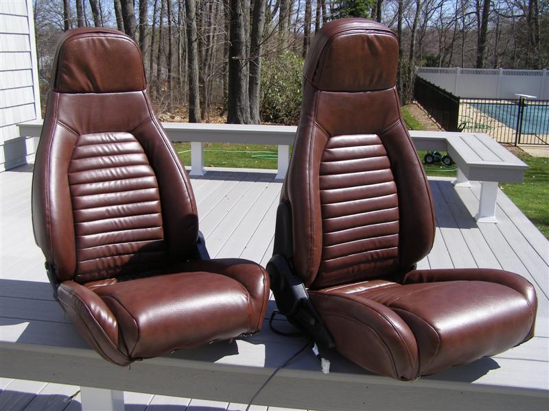
This is
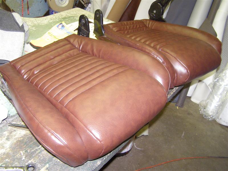
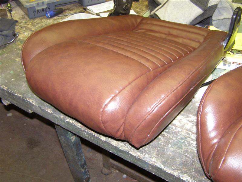
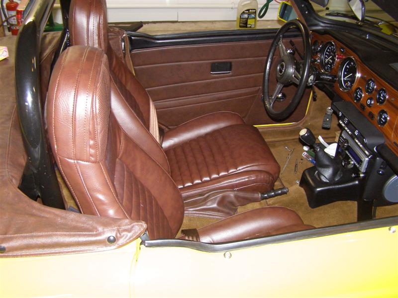
what I purchased from an ad on Craigslist. Again, I got very lucky, as
these were in very good condition.
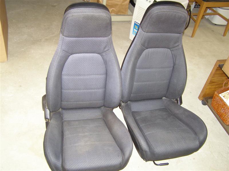
It's almost
a shame to waste the covers, but Eddie will need them to make
matching Chestnut covers,
along with rolled and pleated inserts, very similar to the
original TR6 pattern.
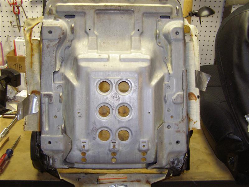
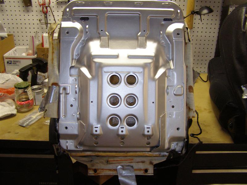
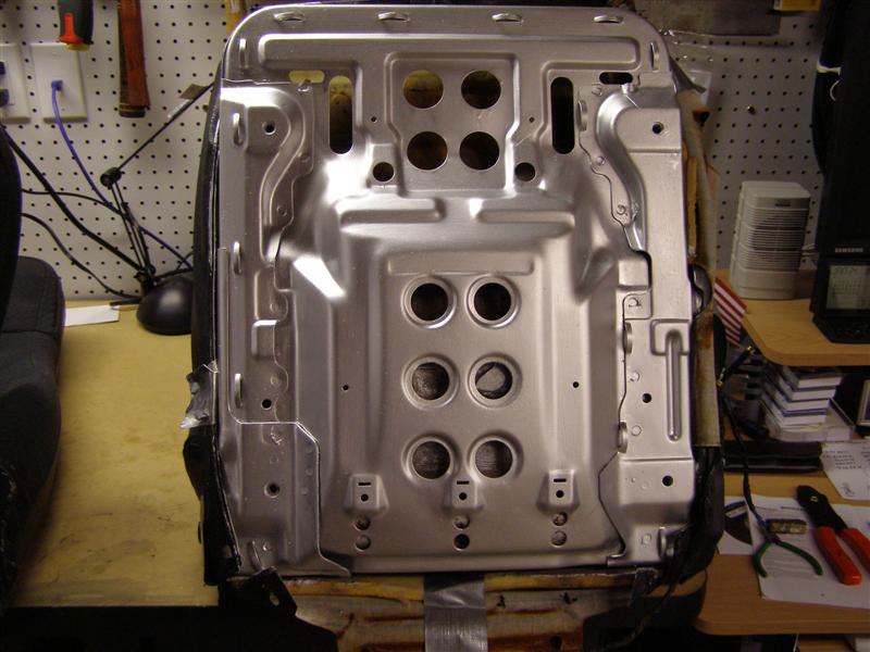
First step,
remove tracks and get the surface rust off the seat cushion
pans.
Words of
caution and warning. You NEED these tracks to make this
work.
Do NOT
leave the salvage yard without them or buy seats without them.
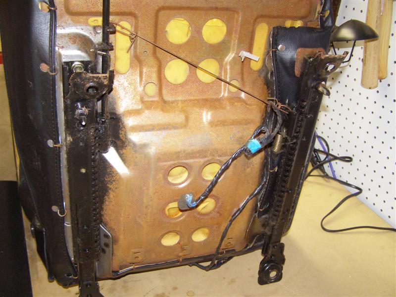
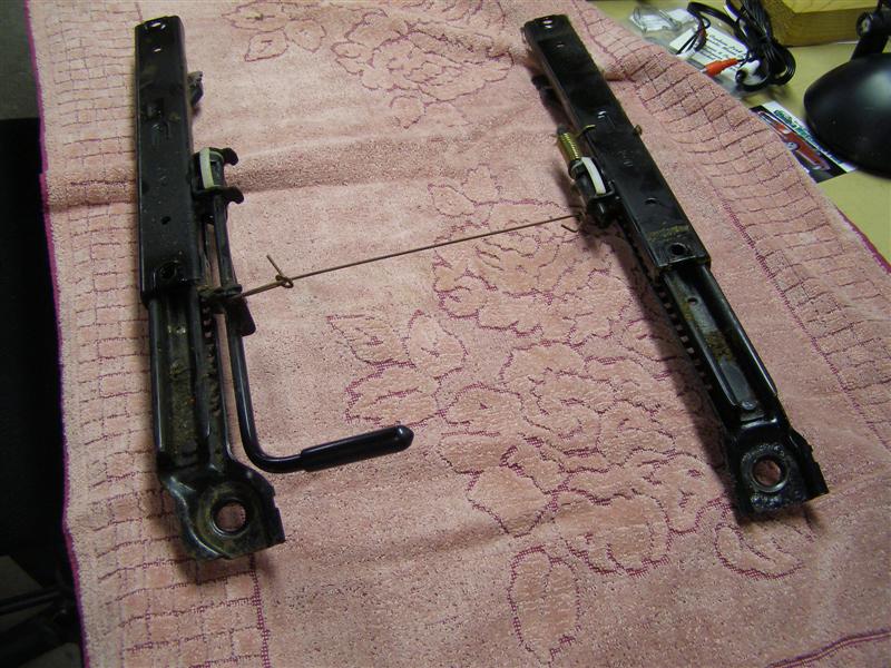
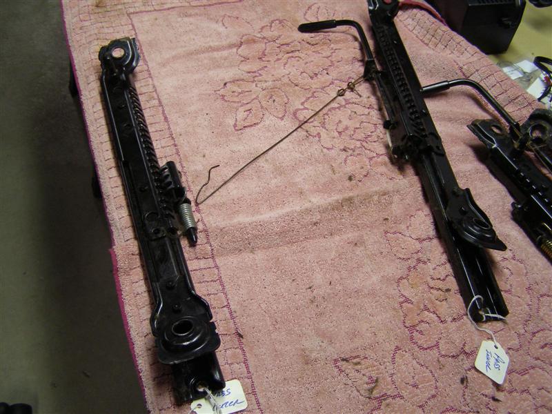
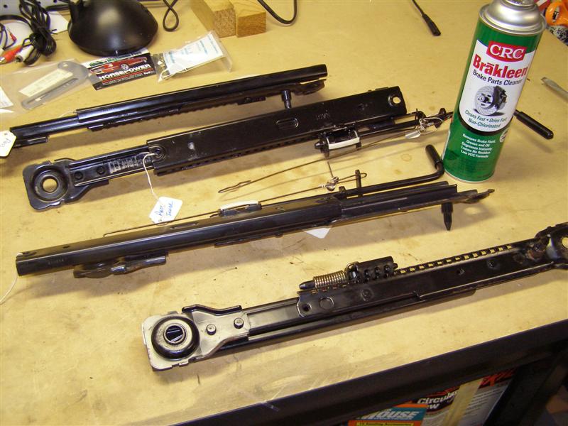
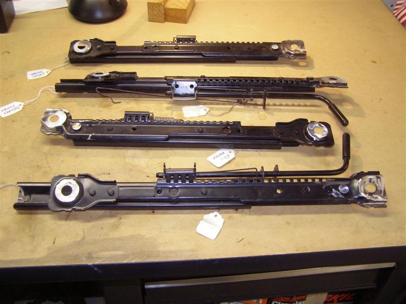
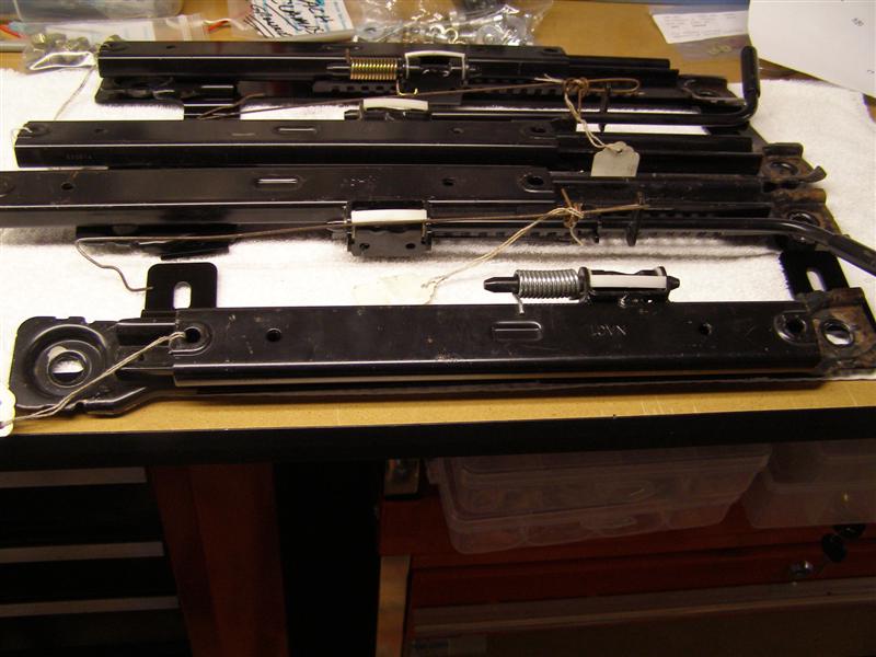
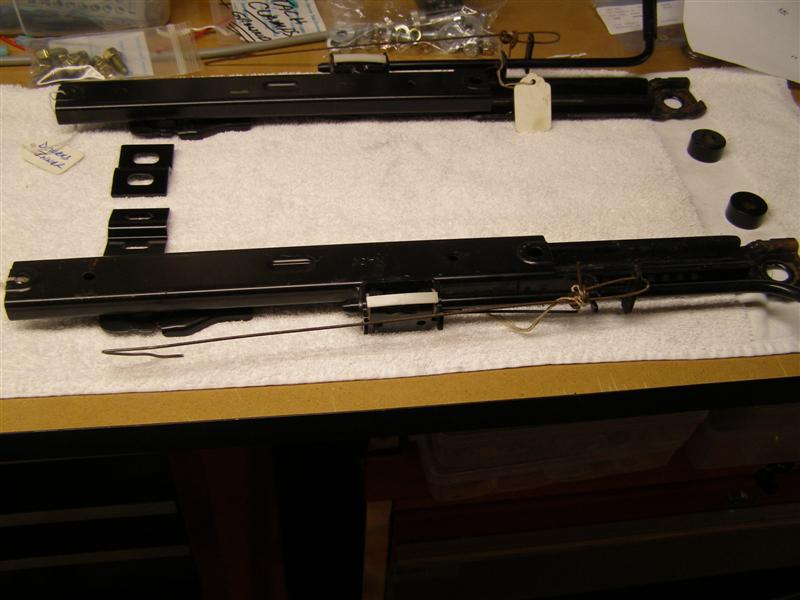
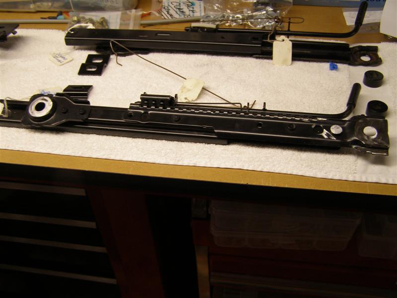
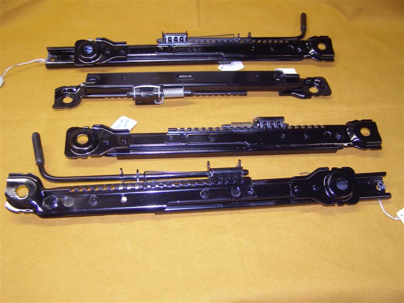
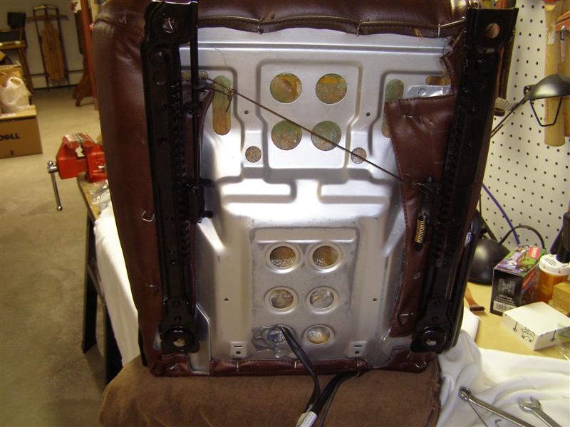
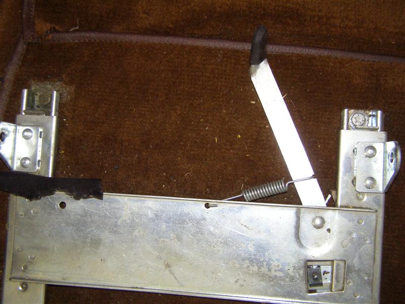
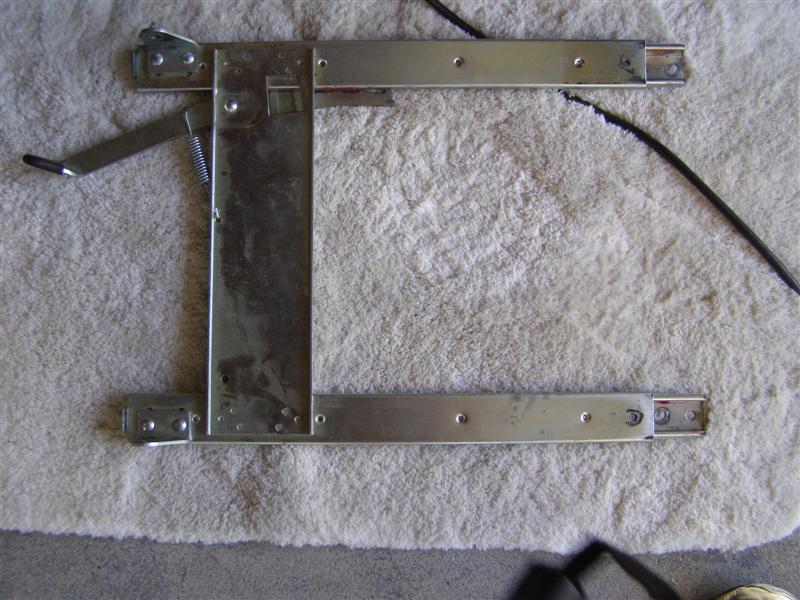
But first,
I'm showing the proper orientation of the seat tracks and the
wire cable between them.
This is the
drivers seat and pay attention to the way the cable is run.
Bob points this out on his site as well.
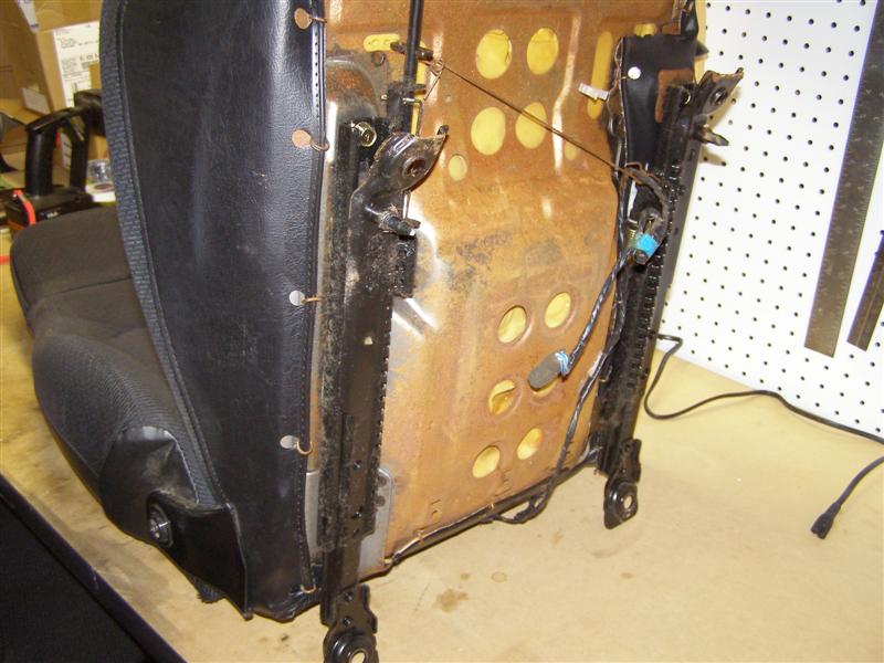
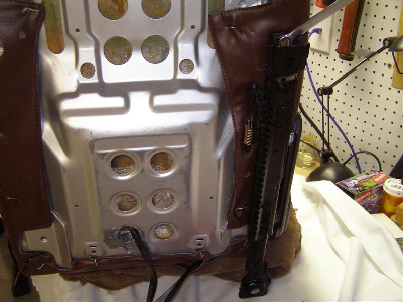
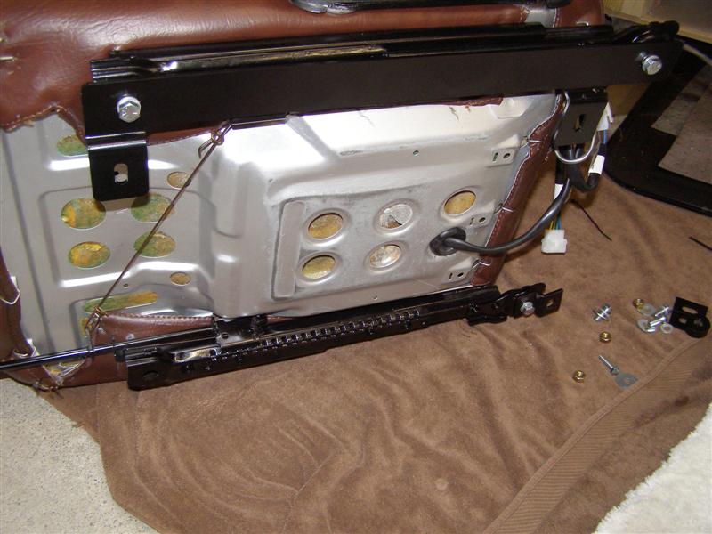
This is the drivers seat with
the track still bolted on. There are four (4) 12mm bolts
that hold the tracks
to the seat frame. You can see the two forward bolts at
the end of each track pictured here. The
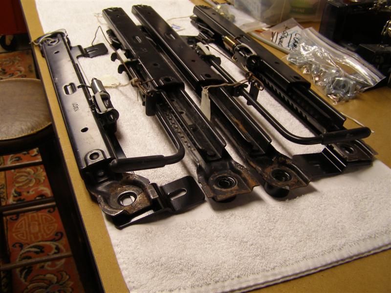
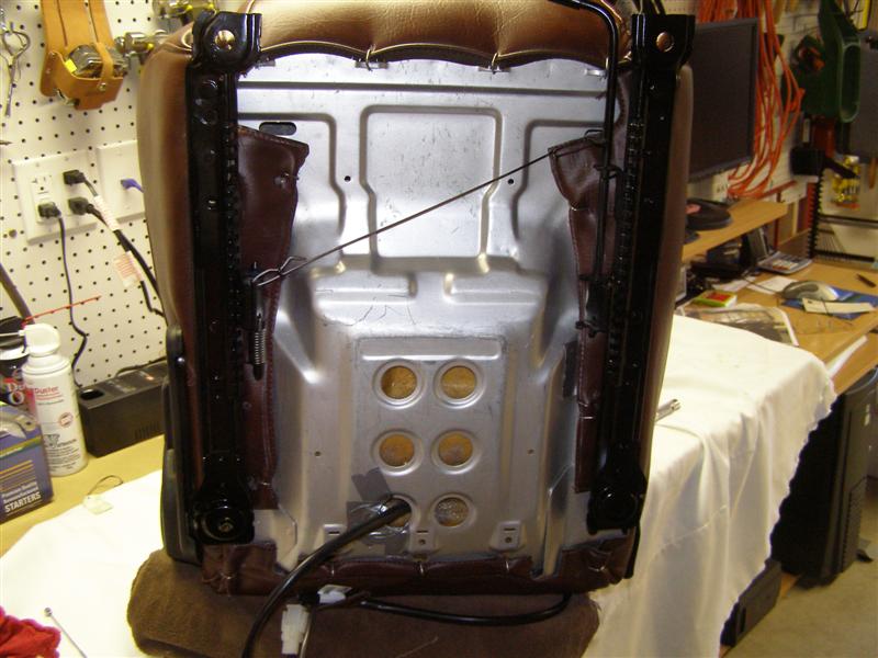
passenger seat is the same and the lever to allow the track to
slide is on the opposite or inside of that seat as well.
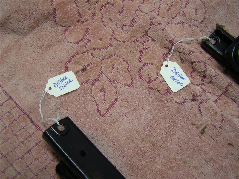
The levers always face in and are on the inside. It is best to
put a tag on each track so you don't mix them up.
While everything is still
connected, you can use the lever to move the seat tracks to the
front, which will expose
the rear bolts and remove them first. Then I did the
opposite and removed the front. It is a lot easier to do
this
if you let the seat sit upside down on the bench with the
cushion facing down and remove everything while it is
flat. Unfortunately, I could not hold the seat and tack
the pictures at the same time, so you'll have to take my word
for it.
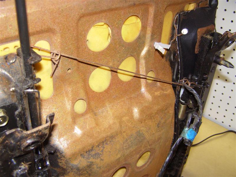
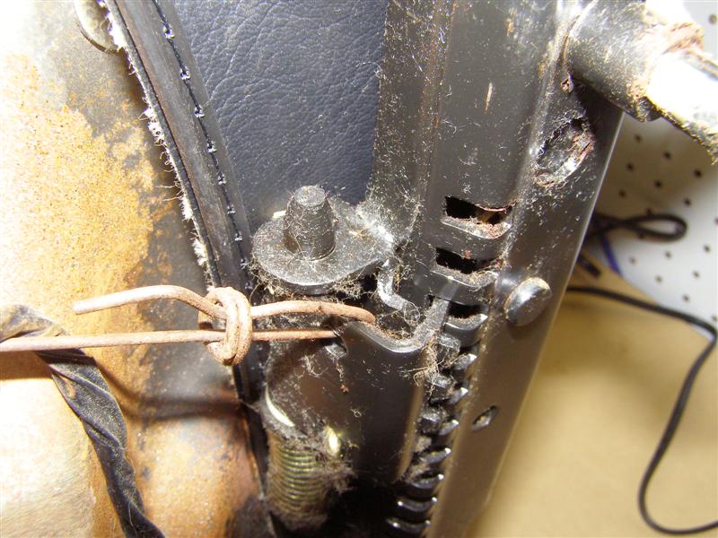
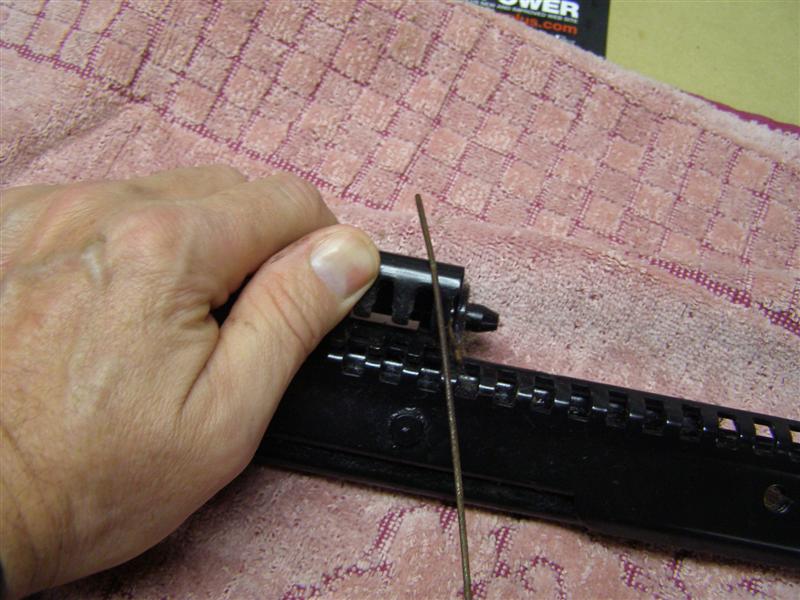
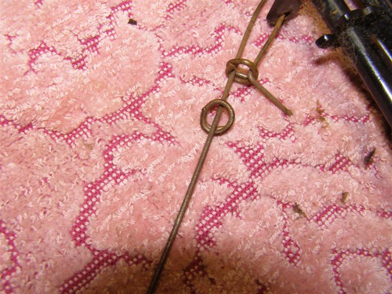
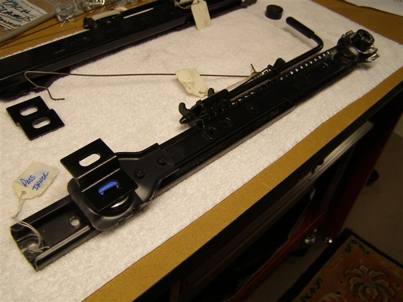
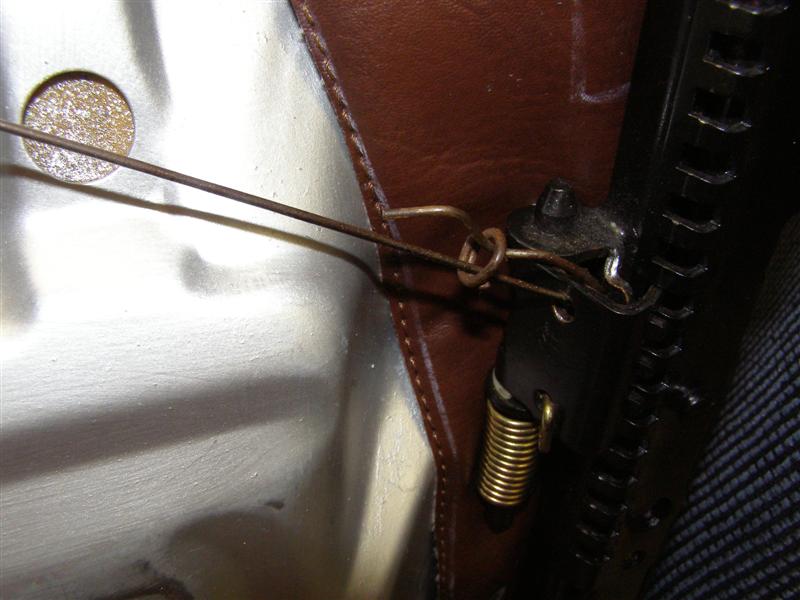
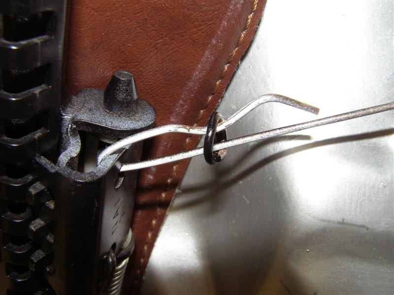
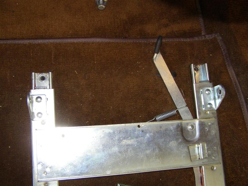
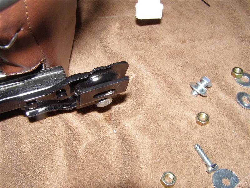
This is the inner connection
in the inner side and this is the easiest side to slide the hog
ring over to separate the tracks..
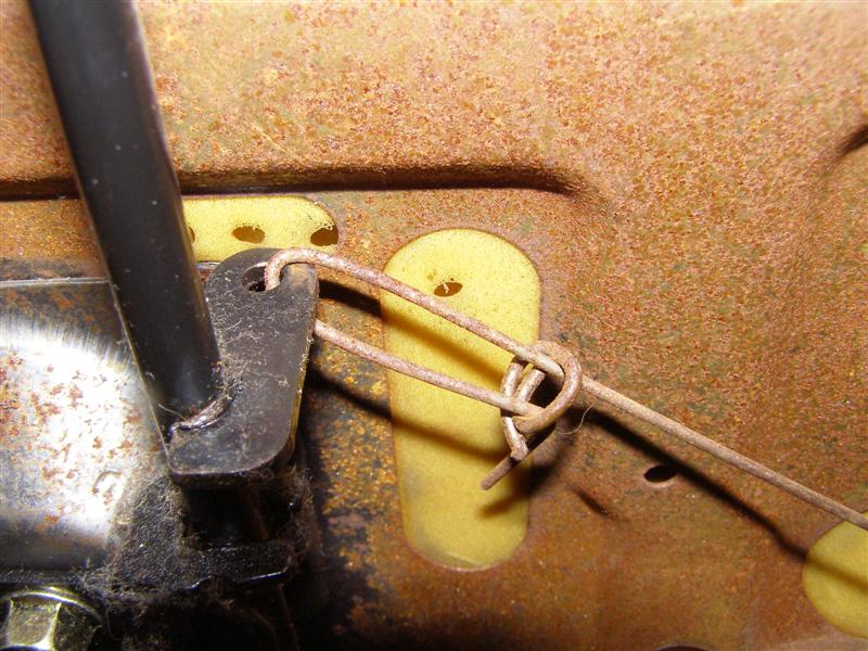
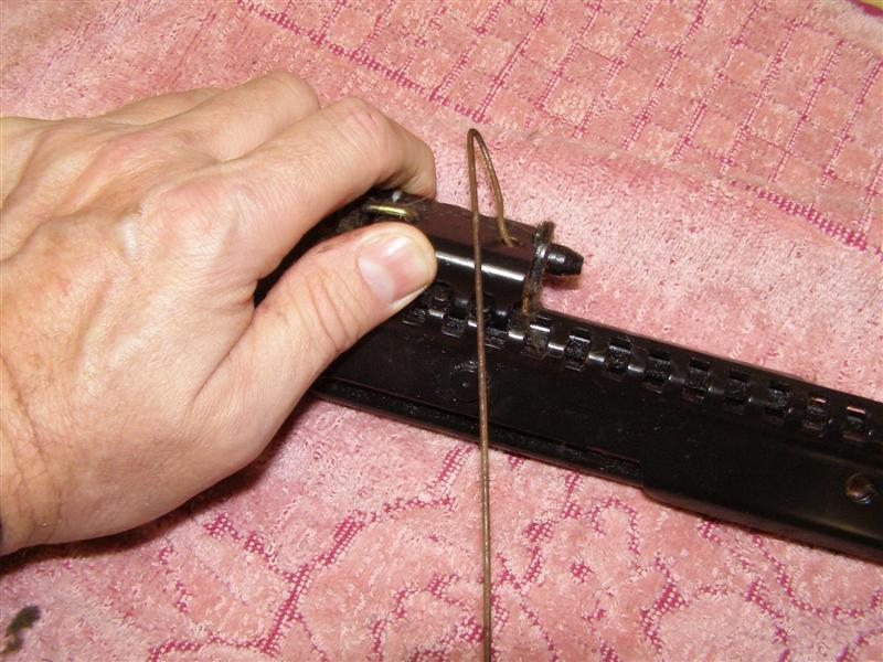
This is the drivers side and
you can see that you would have to bend the cable and there is
no reason for that.
Once the tracks are off, you
can easily push the wire down and slide the hog ring away,
allowing this end to be removed from the hole on the track
release.
Now the drivers side is off
and facing down as the seat would sit on top of it.
It's a little awkward, but I
preferred to remove the tracks as a set to keep the cable rod
from bending out of shape.
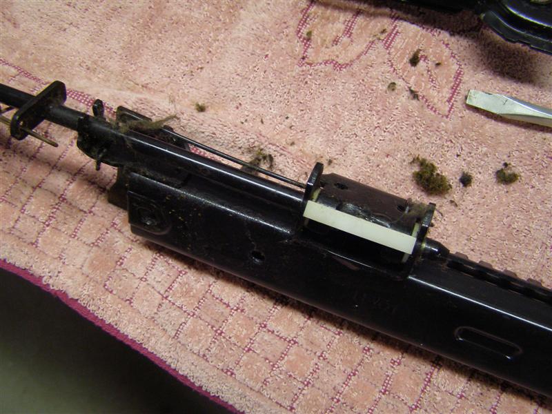
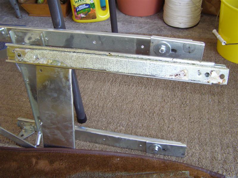
You can see the dirt, grease
and crap in the tracks. These will get a good cleaning and
need some metal work done later as well.
Please note how these are
bent down in the front and rear. They will need to be
straightened and slightly twisted to match
the custom bracket kit from Joe Alexander at
Alexander Racing Enterprises that make this all work.
More on those in a little
while.
If you move this over while
holding the track down, it is much easier to get these
separated.
Once you turn it over the
cable easily comes out or goes back in.
I try to label everything
that comes apart, especially when I don't get back to it for a
week or so.
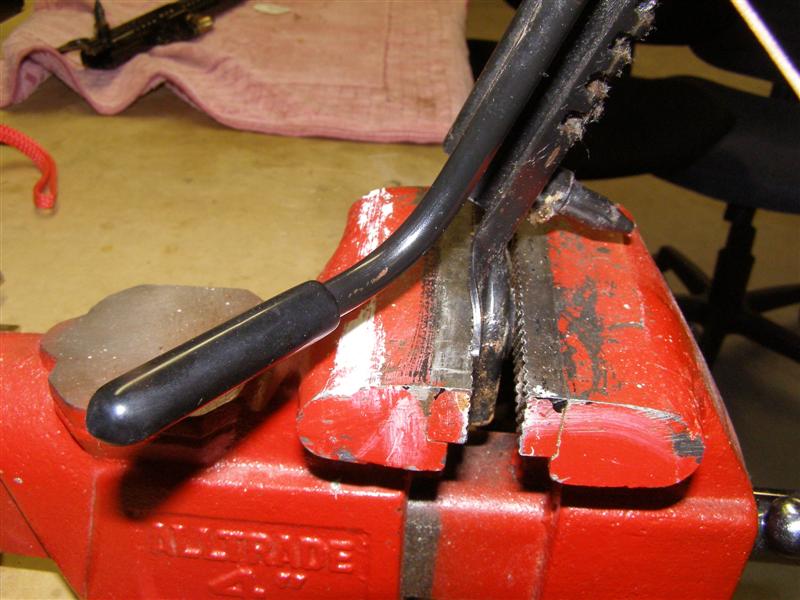
Now for the bending of the
ends. I bent this before I realized that I didn't take the
picture, but wasn't going backwards again.
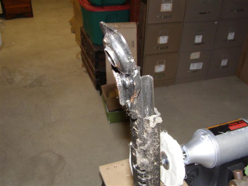
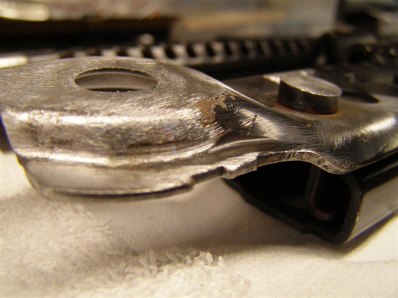
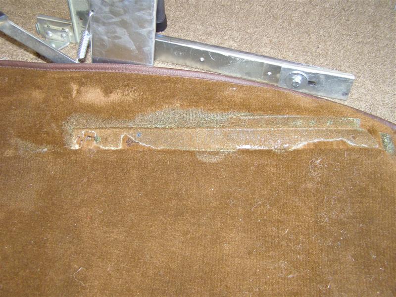
This will show you how much
the other side is bent to fit the Miata floor. We need
them to be perfectly
flat and that ridge around the circular opening will need to be
ground down completely flat as well.
Amazing the amount of dust,
fuzz, pet hair and dirt that sticks to grease after 20 or so
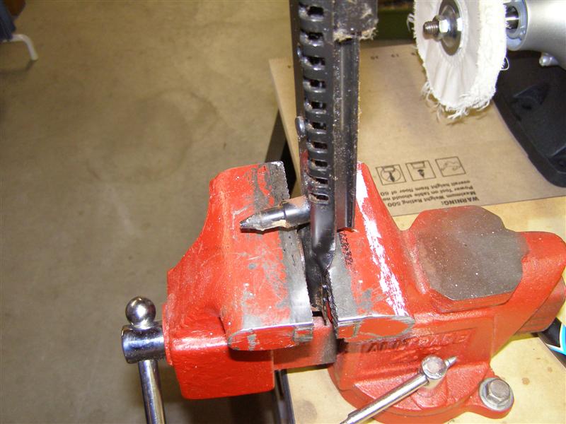
years.
This angle needs to become 90
degrees or perpendicular to the vise, as well as straight across
with the opening.
Once again, make leverage you
friend and don't beat these into submission.
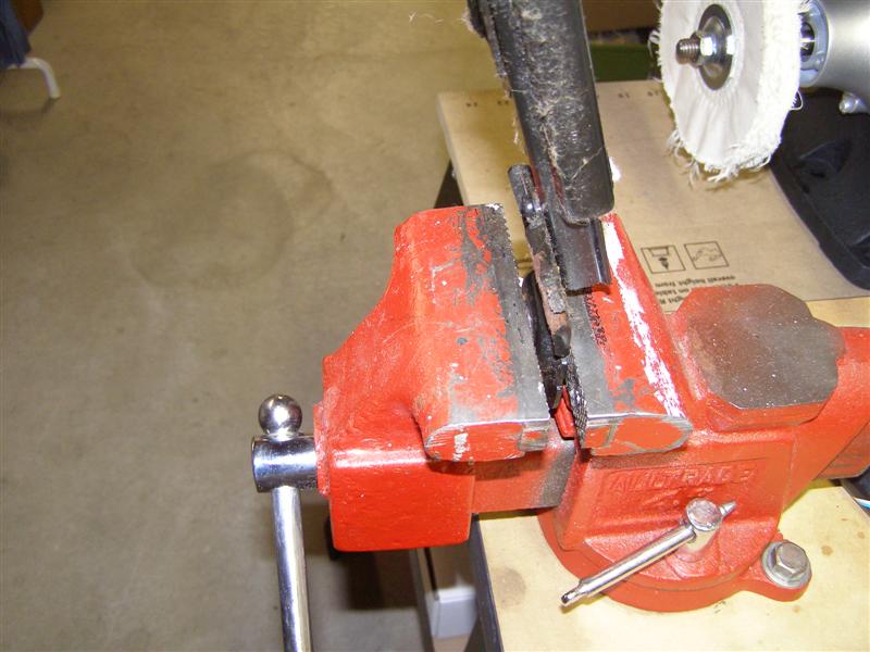
It's getting there,.
Bend slowly so as not over stretch the metal.

That looks a lot better, but
there is still a twist on the ends that needs a little more
tweaking.
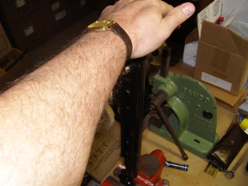
The inner side is a little
more tricky, since the track release can get in the way when you
are bending it straight.
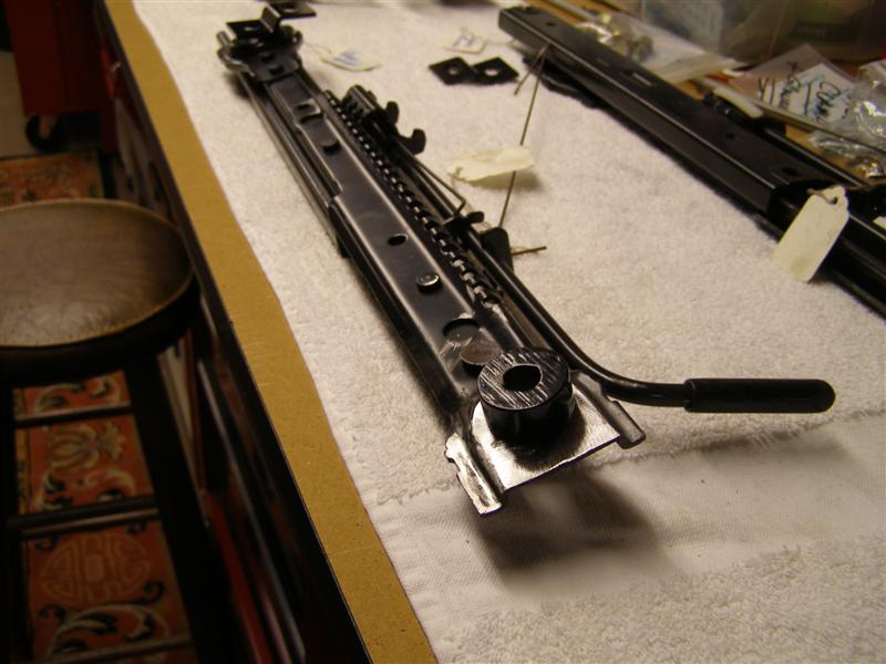
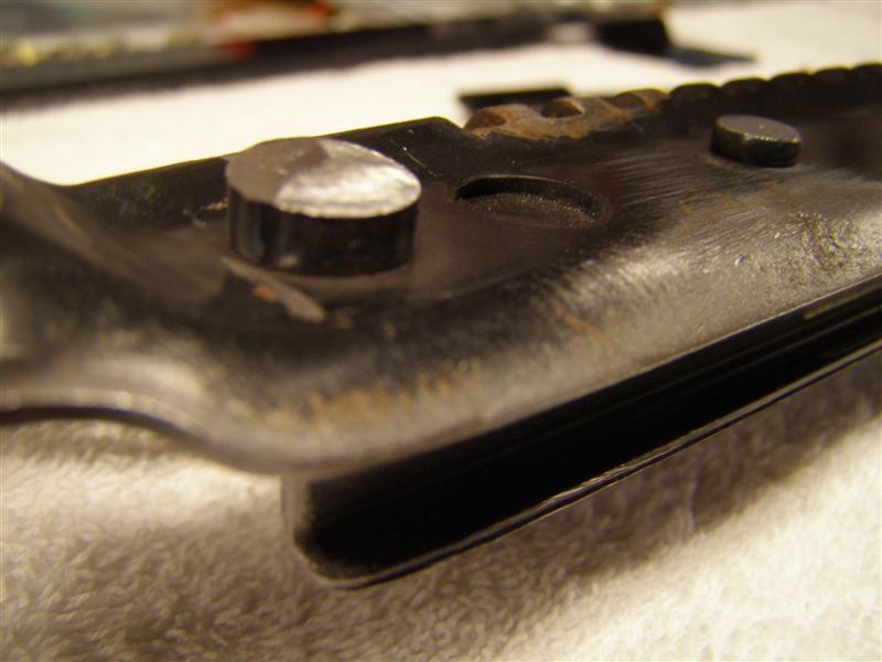
The stud that is a locator on
the Miata needs to be ground down to about 1/8"-1/4" high.
DO NOT grind this off flush
to the track because it acts as a big rivet and holds the two
sections together.
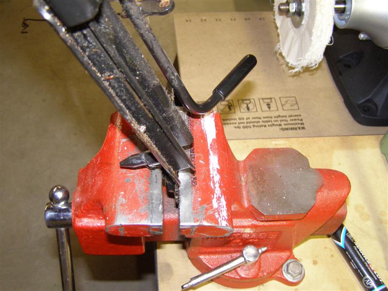
It's getting there. The
straightness is OK, but the twist needs a little more tweaking.
Now the passenger side needs
the same things done to them.
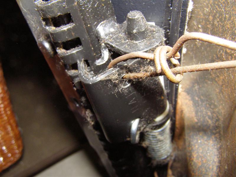
The hog ring is moved away
from the other side. I tied this one to the one in the
right of the picture so it wouldn't fall off.
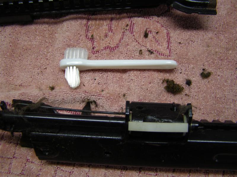
Now for the greasy junk
removal.
A pointy toothbrush works
well to get down in the cracks and low areas. Bob had to
take his
completely apart, but I don't so I'm just cleaning, grinding
then repaint and re-lube everything back up.
For the final wash down, but
do this outside. This stuff if strong and flammable.
I put these away for a while
to get the seats done, then did the other work while the paint
was drying.
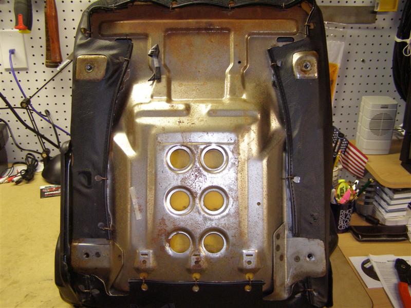
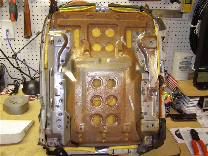
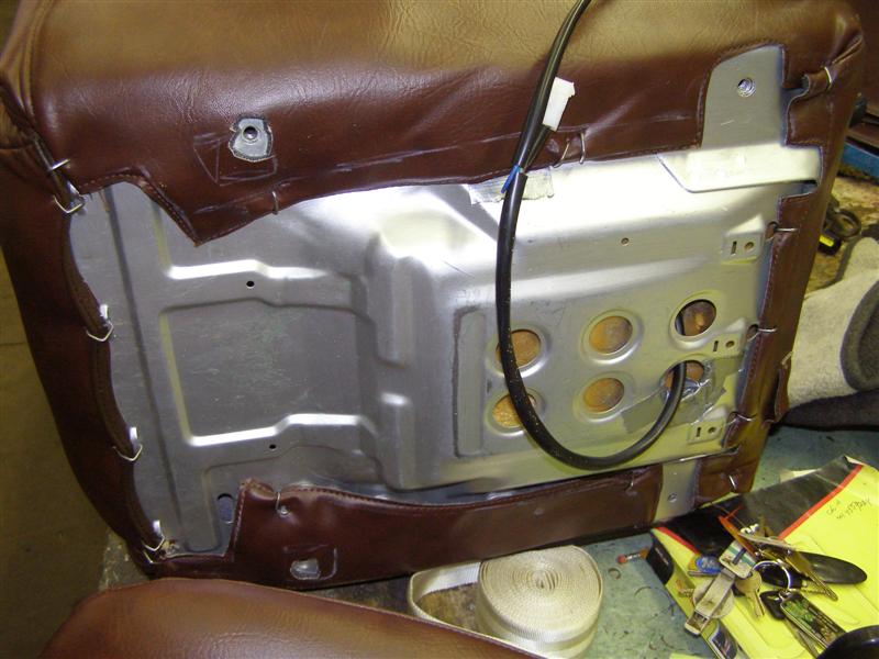
Next, let's
get rid of the tracks and remove the hog rings that hold the
trim on, so we can slide the cushion
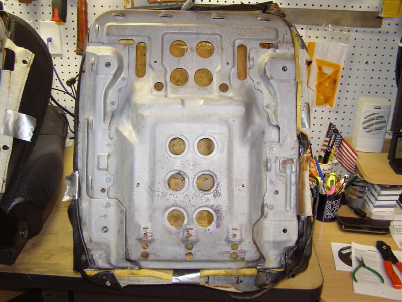
away from the seat frame and check for any surface rust above.
This car was never flooded nor did it sit
in a salvage yard without a top, so these are quite normal, or actually
good for a 20 year old car.
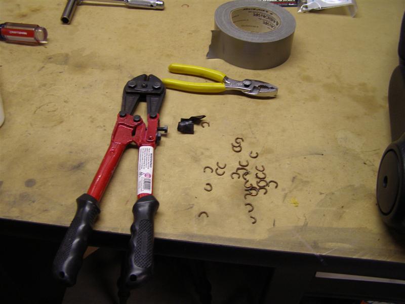
These are
hardened steel and do not move easily once crimped into place.
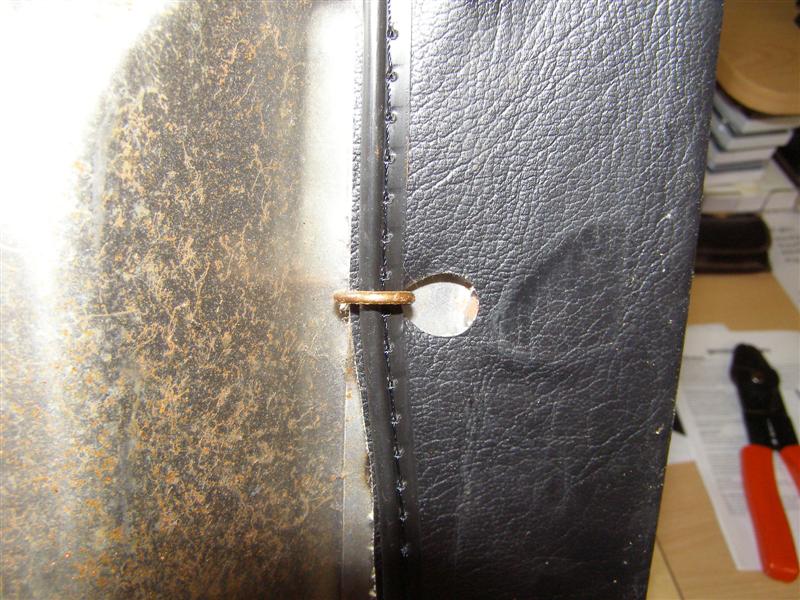
Leverage is
a wonderful thing. Use it to your advantage when you can.
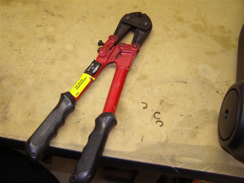
These guys
really help to cut hog rings easily and there are quite a few to
cut.
That
surface rust really bugs me and has to go, but I don't want to
grind it off.
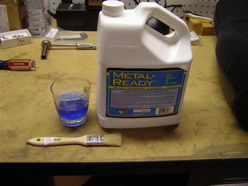
I used a commercially
available product that I used on my frame and it worked great
there as well.
This
product is made by POR15 and must be used with great caution and
common sense. Eye, skin and breathing protection must be
used
in accordance with the specified label instruction and good
common sense. Adequate ventilation and proper cleaning
techniques are a must.
***** DISCLAIMER *****
I accept NO responsibility for any issues resulting from anyone
who follows my procedures or uses this product.
This is
purely a history of what I've done and I'm not promoting any
process or product here.
The first coat is brushed on
and I scrubbed these with a Scotch Brite Pad to loosen up the
surface rust.
I went from one to the other,
brushing on fresh as I moved back and forth. I also used a
small brass brush
to get the crap out of the little crevasses and cracks and to
get any tough spots with some leverage. the instructions
say to keep it wet.
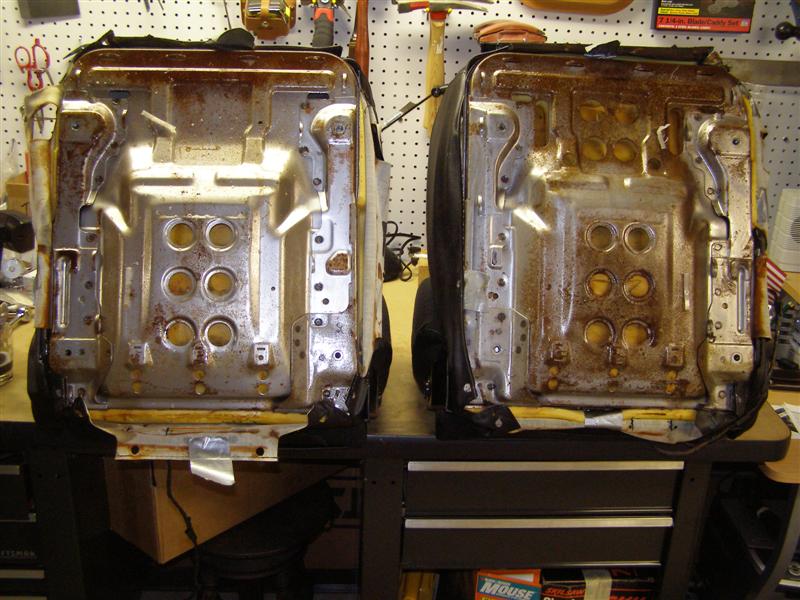
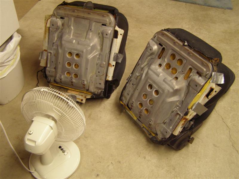
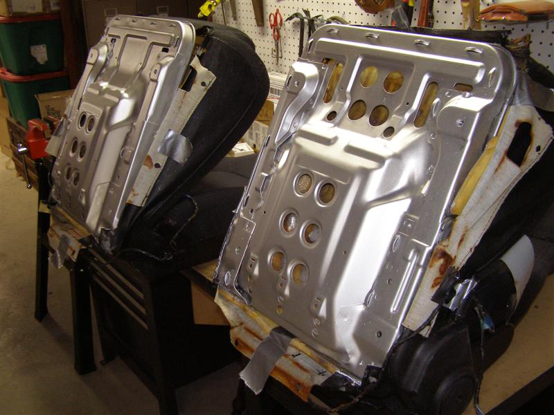
This is after three
applications, scrubbing and a wash down with warm soapy water.
Both seats came out really
well, but you can see the strength of the chemical took all of
the shine out of the metal.
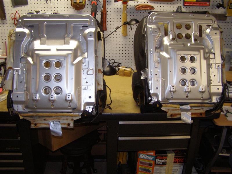
A few hours to insure
everything is dry before painting. These are etched and
ready to be painted.
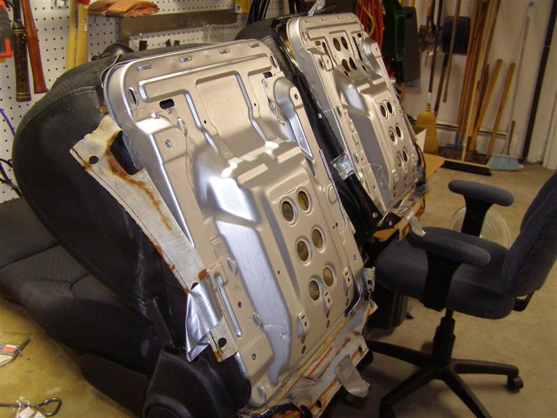
Two coats of Rustoleum
Aluminum paint and they look great again.
It was cold and raining
outside and I didn't want to smell up the house with by spraying
these, so I brushed
each coat on. I gave each coat 24 hours to dry at 70
degrees in my basement which is also very dry.
Caution must be taken so as
not to damage the foam. It is molded to each seat and fits
down over the frames.
I had no rust above, so I
didn't need to take the assemblies apart, but I didn't want to
leave the rust below.
Enough of that stuff, time to
move onto the next part and that is the tracks that I removed
earlier.
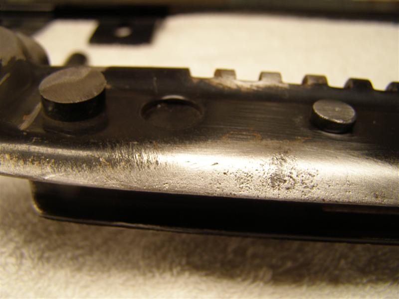
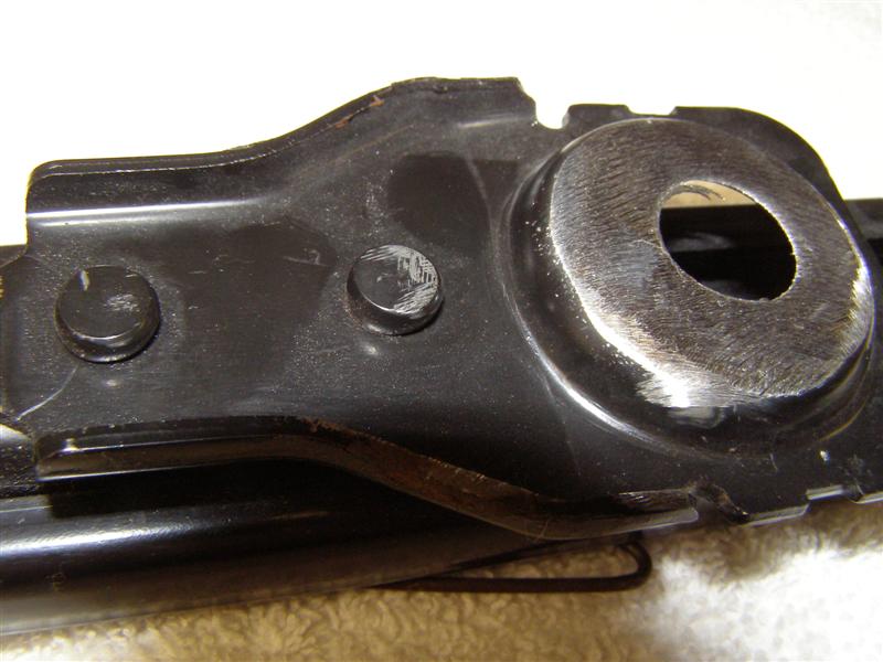
This is how the tracks should
look when the raised portions are ground down and the studs are
cut off.
Remember to leave the stud about 1/8" above the metal that it
helps to hold down, as you will see it is the
second rivet that holds the front bracket onto the actual slider
mechanism and that should not ever come loose.
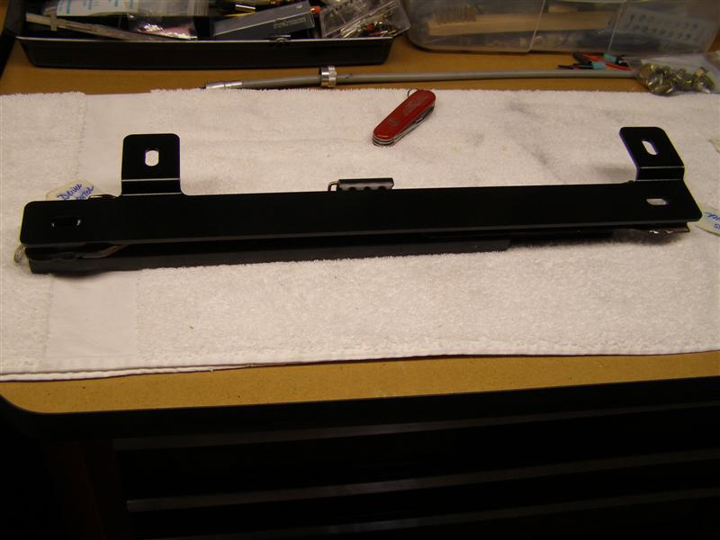
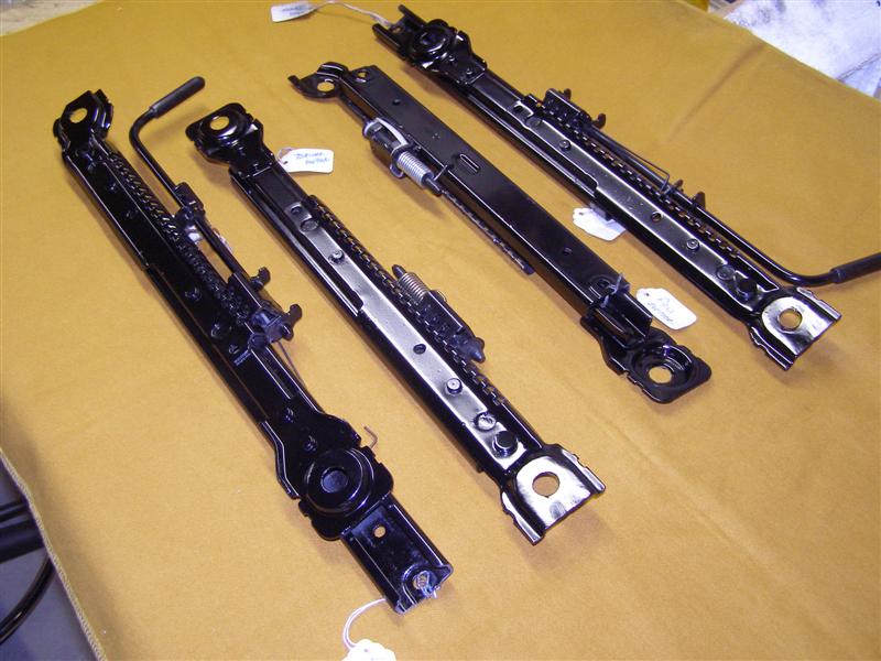
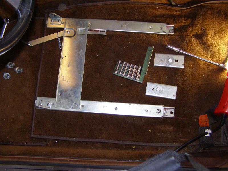
Next, let's look at the seat
track bracket kit from ARE. On a narrow towel on my bench,
this
is how the brackets would look if laid out on the floor of a
TR6.
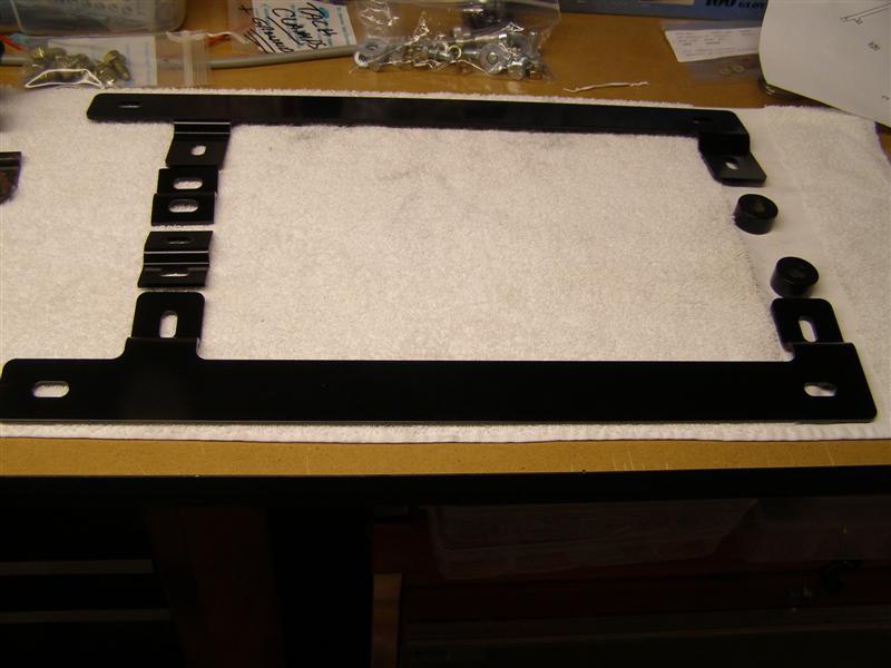
The long brackets go on each
outside rail with the angles raising them up and away from the
carpet.
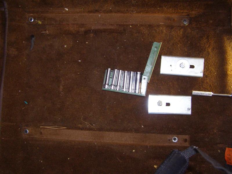
The short brackets go on the inner rear, in the same fashion and
the thick round spacers go up front on the inner rails.
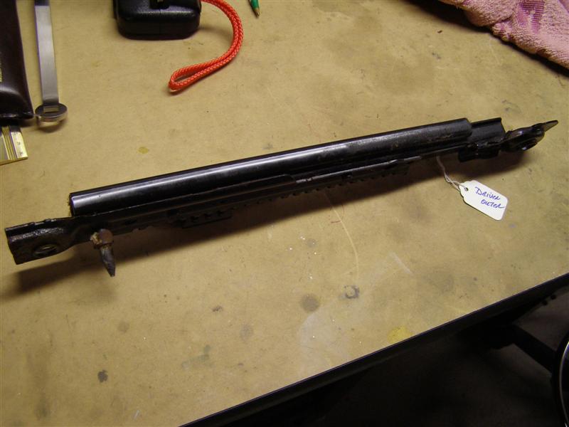
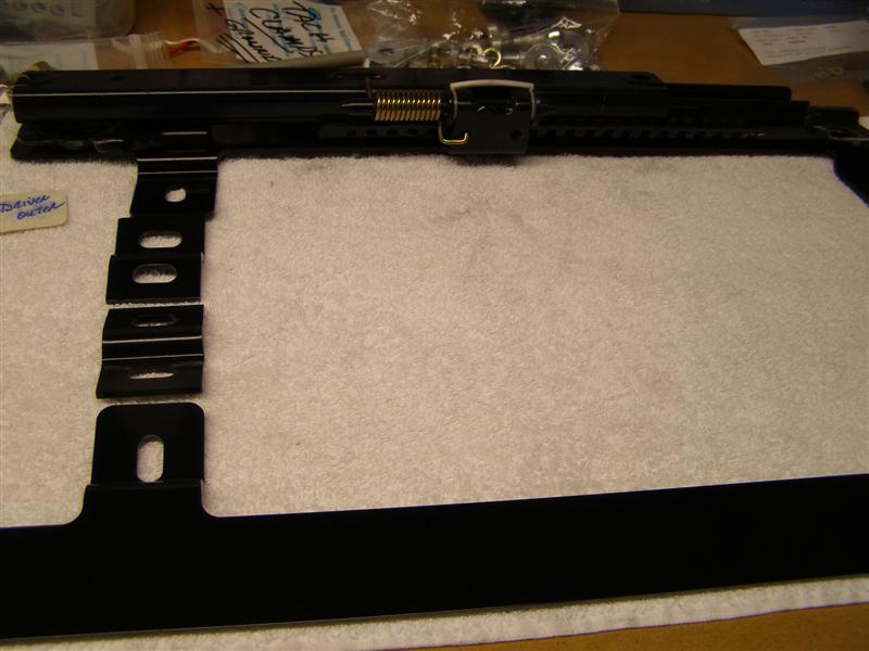
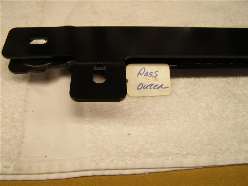
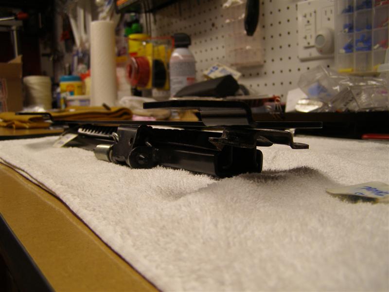
This would be the outer
drivers side rail sitting flat on the outer bracket. The
seat would sit on top.
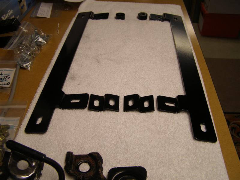
This shows all four of the
tracks in their respective positions on the brackets.
Another view showing the
levers always on the inside rail.
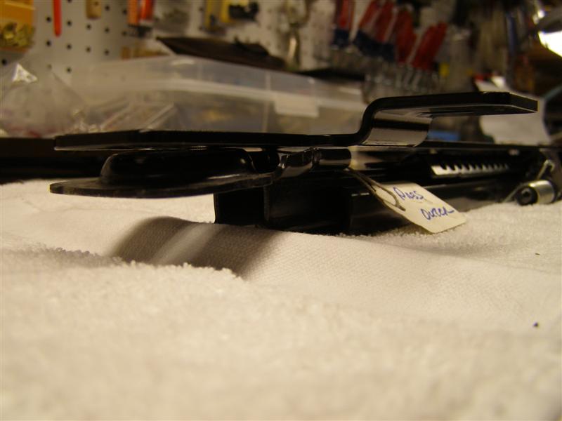
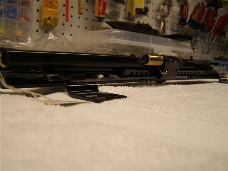
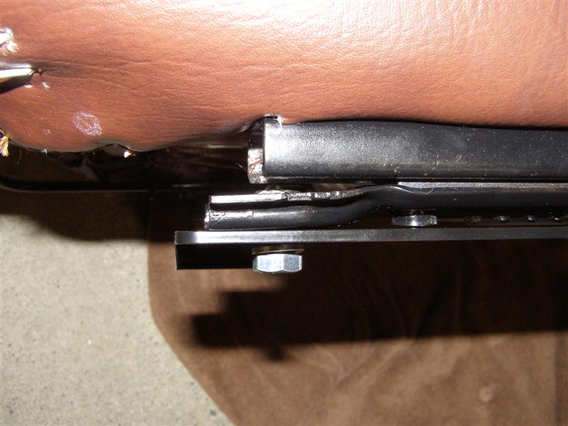
This will show how the fit
between the track and bracket needs to be flat and tight.
A better view with both
upside down shows the fit where the raised ring was ground off
to be nearly dead on.
Just a little tweaking in the
vise and this will be spot on. There is 1/8" clearance
between the track and
the bracket, so the seat assembly should always slide back and
forth with no problems at all.
The reason that I didn't
paint these yet was to make sure they were perfectly flat and to
show what needs
to be removed. You can see the former stud sticking up
about 1/8" in the front of the track, as it should be.
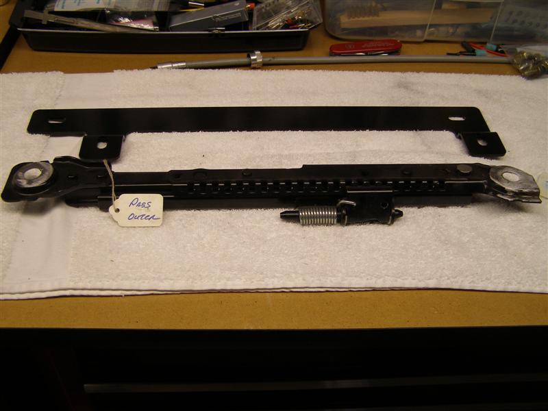
Another view of the
driver outer sitting on the bracket as it should to.
And again, another nice tight
fit.
Upside down for illustration
only. The seat bolts for the track to the frame are in the
bag on the right.
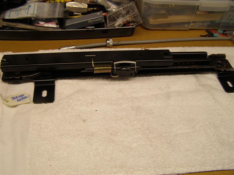
These are the inner tracks
with the levers.
This is upside down, but it
shows how the bracket will lift the rear off the floor and the
front has the spacer.
Another illustrative view of
the same.
And a view of the ground down
front and rear mounting holes and the stud cut down up front.
These studs are on both the
inner and outer tracks.
Just so there are no
mistakes, this is what I'm talking about with the cut off of the
stud and what should remain.
Just keep them below this
bend and it will be fine. They will never come loose with
that much metal on back.
And this is how the ridge
should look after grinding flat on all eight (8) contact points.
And for the rear, these are
lower than the contact point, so they are fine once the ridge is
ground flat.
Two coats of primer and two
coats of black engine paint should keep these nice for a long
time.
Plenty of time to dry and
harden for the next few weeks while the rest of this comes
together.
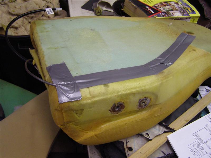
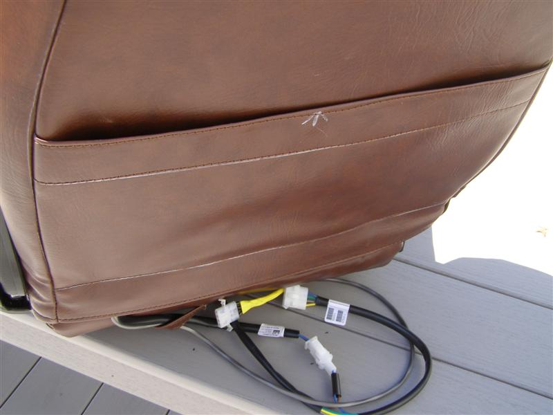
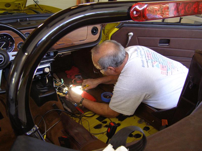
Time to start the wiring harnesses.
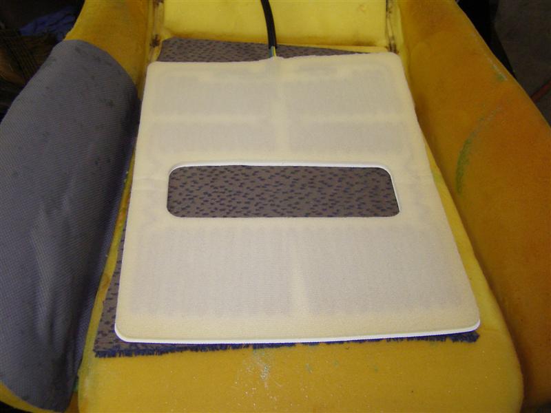
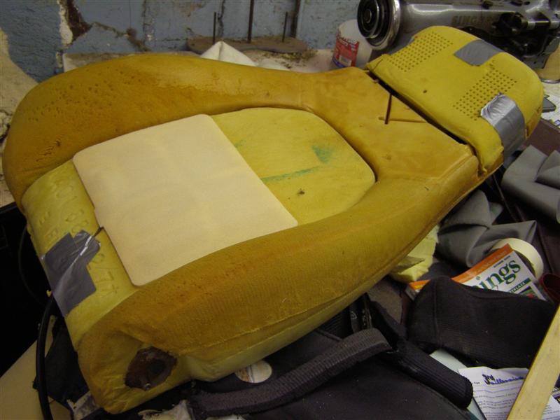
This is a picture of the
seat foam with one of the original speakers and the original
Miata wiring.
My new wiring is shown to the
left of the original blue and white wiring.
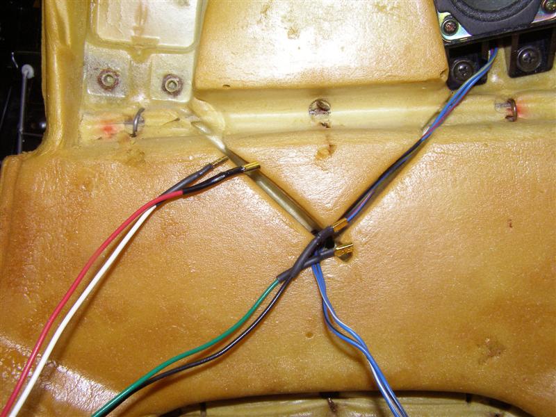
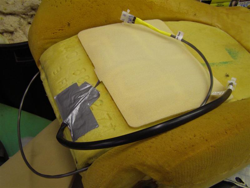
The speaker box will go in
the spot on the left and new speakers will replace these OEM
units.
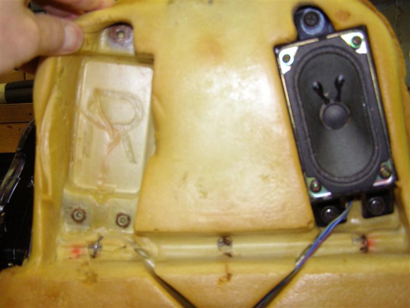
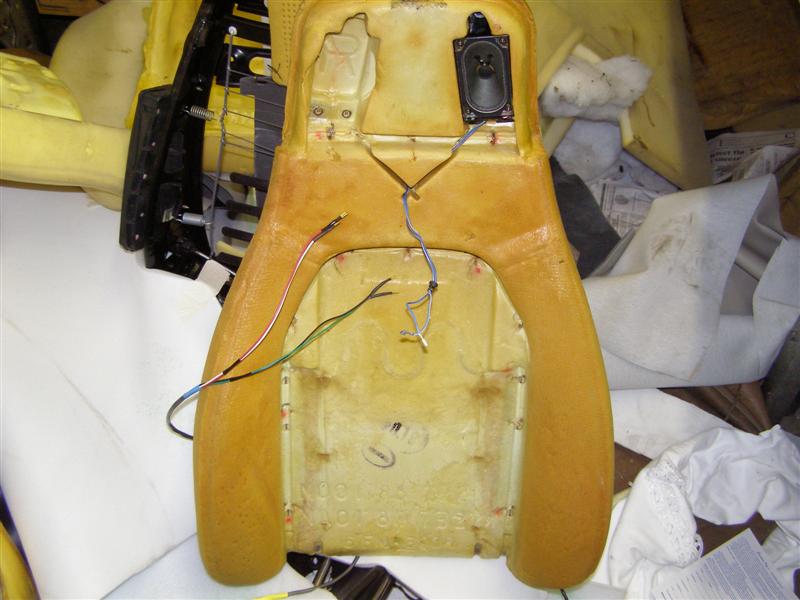
The wiring then goes through
the center hole above the top of the radius in the center panel
recess and out the back.
That is where the "V" is
shown with blue wires coming out and then the wires follow a
path that is cut out down the back of the seat
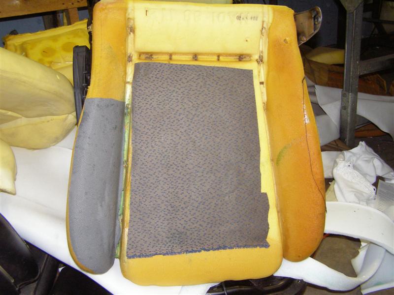
Just a shot of the bottom
cushion and that is the way it was when uncovered.
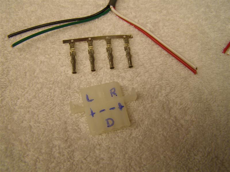
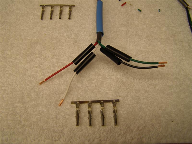
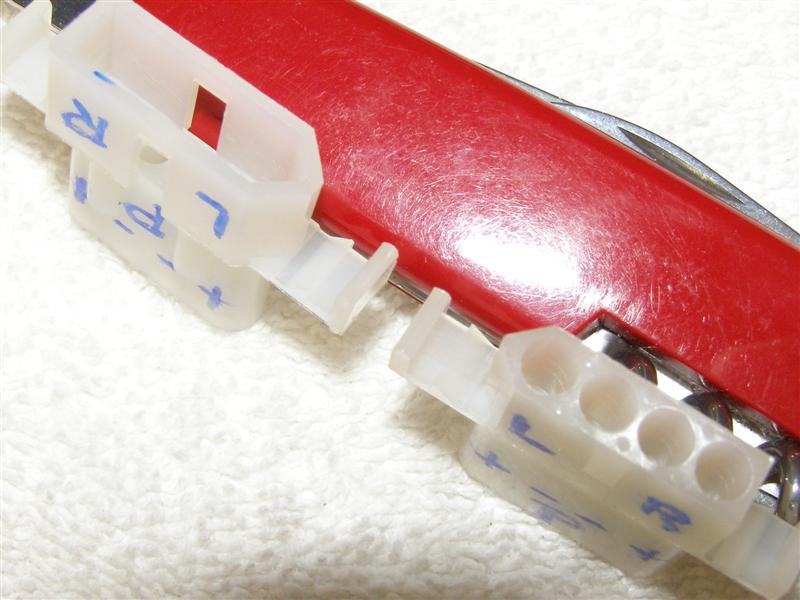
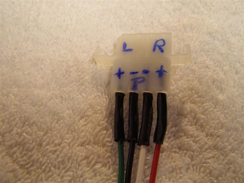
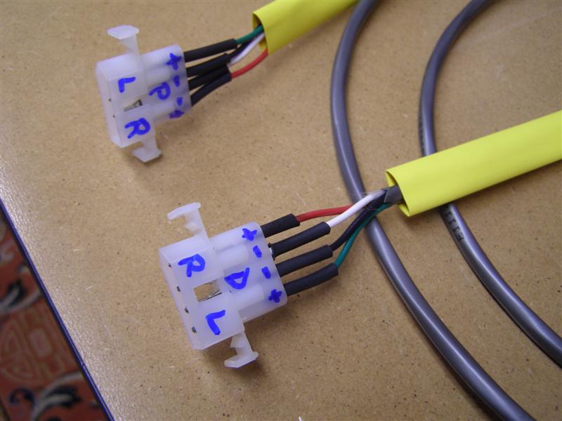
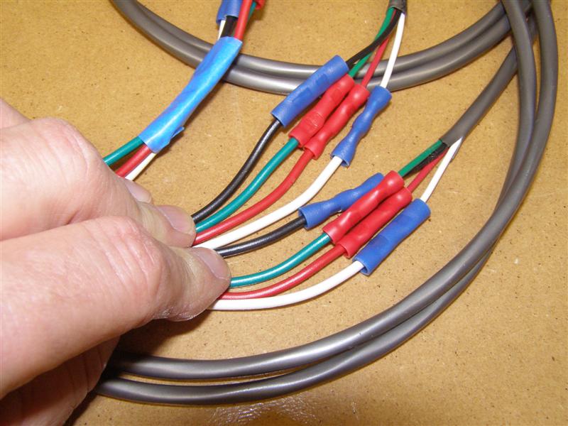
Radio Shack connectors courtesy BobbyD instructions.
Pick any color combo together
that you want, just write it down and make sure the opposite
side matches.
Truth be told, I don't take
all of the pictures just for everyone else's benefit.
The blue heat shrink was not
near big enough, but the point is you need to do this before you
crimp and solder
the ends on the wires. Especially when one side is already
done and there is no way to get it back over the connector.
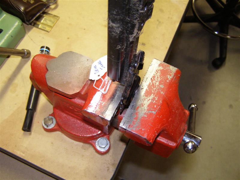
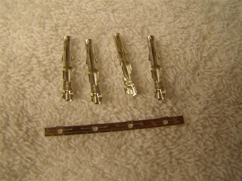
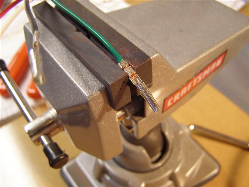
The best way to break these
off is by putting the strip in the vise then just move them back
and forth.
After several moves back and forth, the snap off cleanly and no
bent or crushed connector ends.
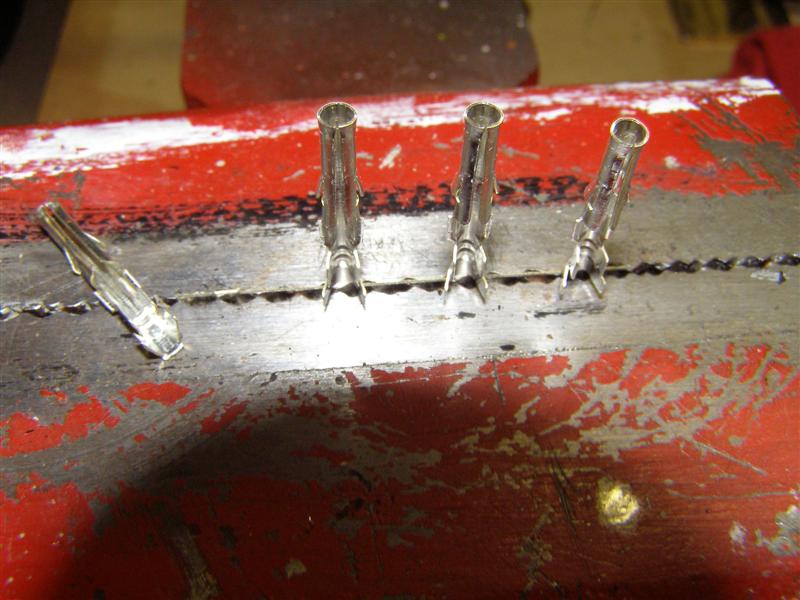
No damage to the connectors
and clean even breaks.
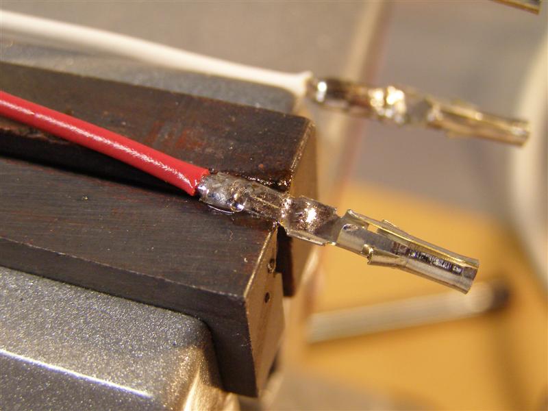
Neatly crimped, but not quite
done yet. Solder comes next.
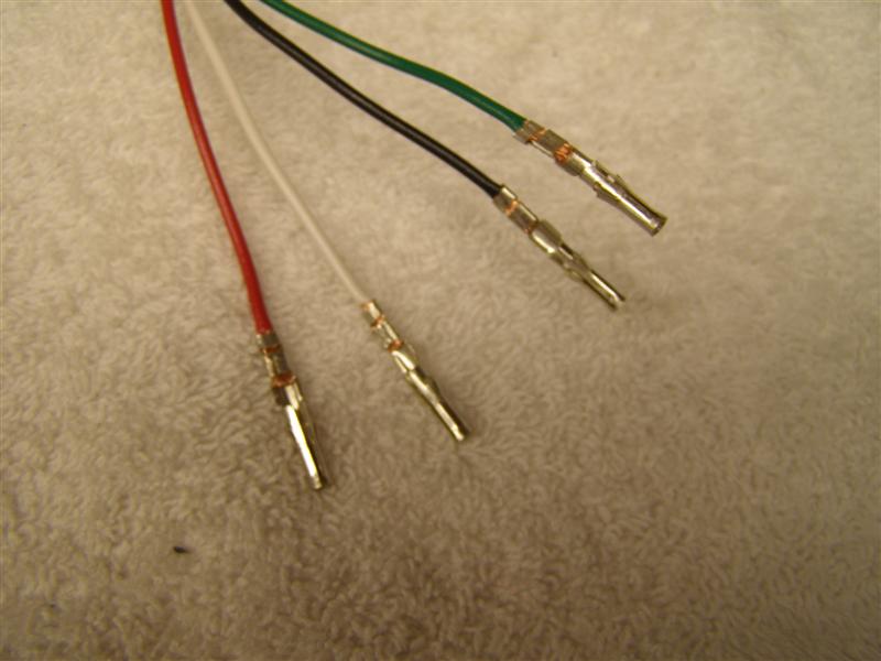
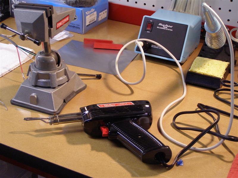
The vise makes just enough of
a heat sink to allow the solder to flow nicely without melting
the wiring insulator.
My trusty Blue Point is great
for board work, but just not hot enough for these, so out comes
the old Weller.
I like soldered joints.
Old school, but never will need touched again.
Obviously, one will be male
and one will be female. I suggest moving the packages off
the bench that you are not using so as to not mix them up.
The barbs that stick out,
snap right into the plastic connectors. Like Bob, I too am
a fan of heat shrink tubing over connectors.
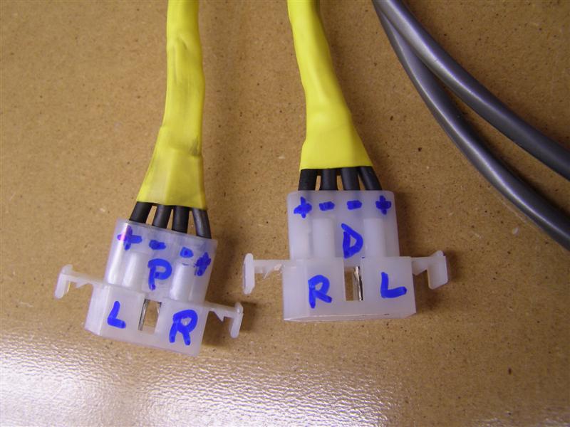
Passenger and Driver lower
harness ready to go.
Radio Shack part numbers are
274-234 & 274-224 for the male and female plastic
connectors.
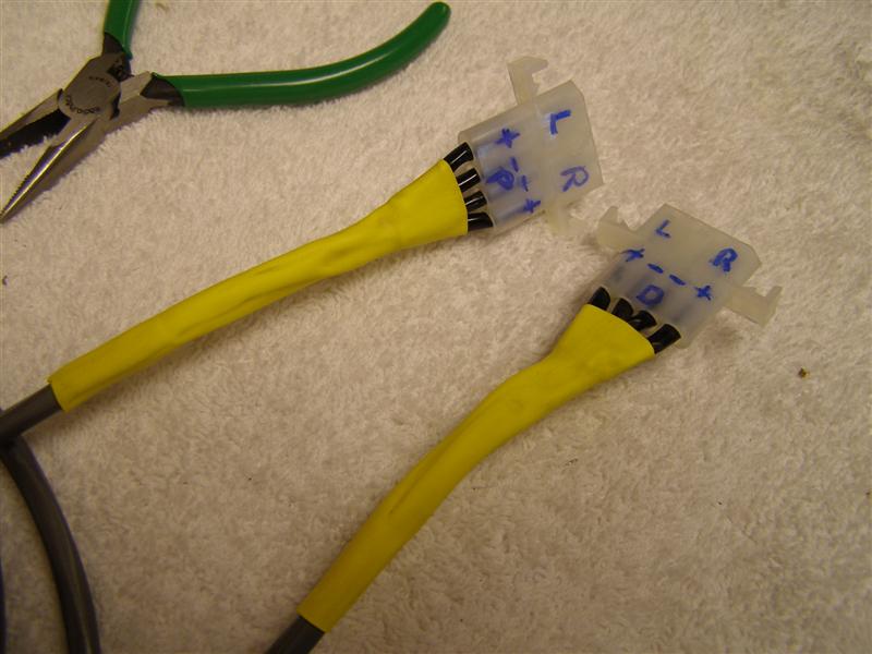
Finished now on both ends.
Heat shrink is a must over the solder in my opinion.
Dorman part numbers are 84546
for the .187" Female & 84547 for the .110" Female connectors.
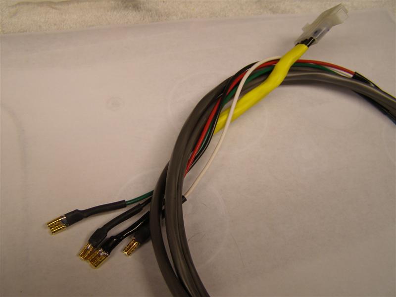
And the mating harnesses to
go to the radio output wiring.
All secure and shrink
wrapped.
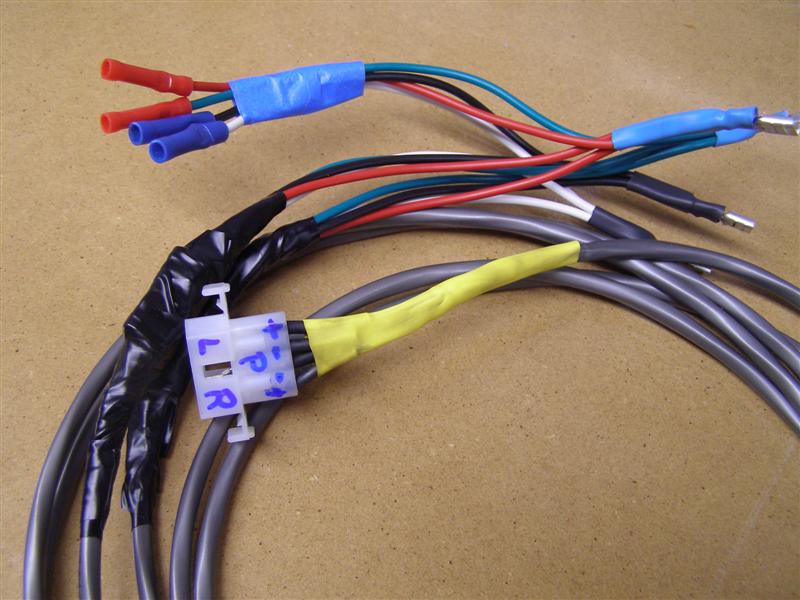
In order to get the speakers
to all work properly, there has to be a crossover to each from
seat for both
the left and the right side speakers as well as maintaining a
connection back to each rear panel speaker.
I did go back and forth with
BobbyD, since he did his prior to me doing mine and had the
splitter wiring mapped out.
Bob is an old communications guy and he works well with wiring
that all looks the same. I don't trust myself, so I color
coded mine.
Right Speakers = Red (+)
White (-) Left Speakers = Green (+) Black (-)
Of course, this will match the previously made harnesses shown
above.
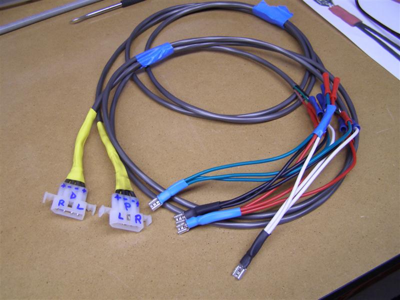
The front harnesses are now
complete and ready to install just prior to when the seats are
installed.
The four connectors in the bottom right will each go to the
radio output leads for the rear speakers.
This is really not quite the
mess it appears to be,
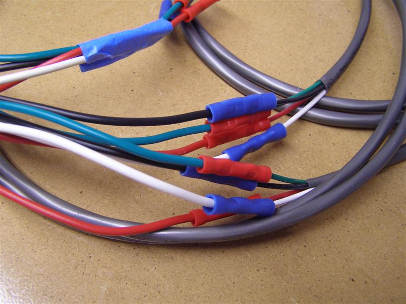
This shows the matching color
wiring to each of the front seats for both left and right
speakers,
with the separate wiring for the rear panel speakers off to the
far left side of the wiring.
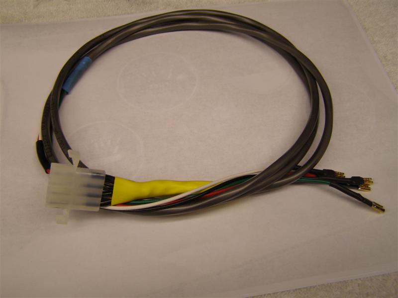
And the final before these
get connected. Although I may switch to a plug in for each
of the rear
speakers in the event I ever want to easily disconnect them from
the rest of the system.
Now for the new Seat
Heaters.............
Another electronics package arrived
today.....more progress.
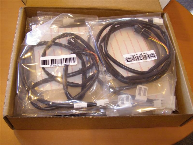
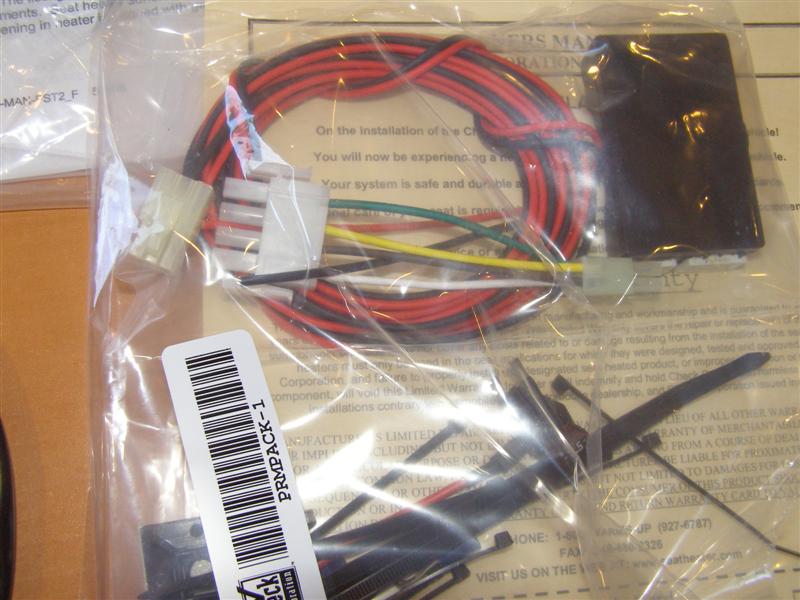
This is the entire package.
Switches on the left, heaters in the middle and modules on the
right.
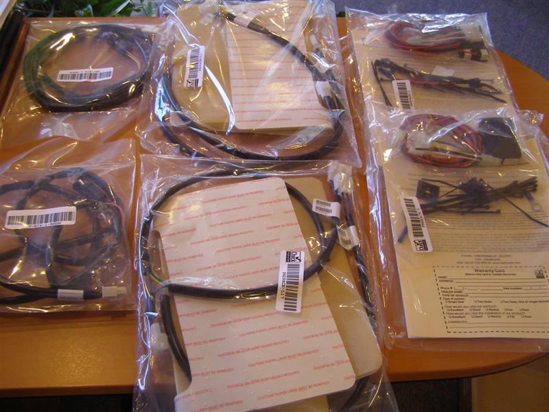
If you look closely, you can
see the grids in there.
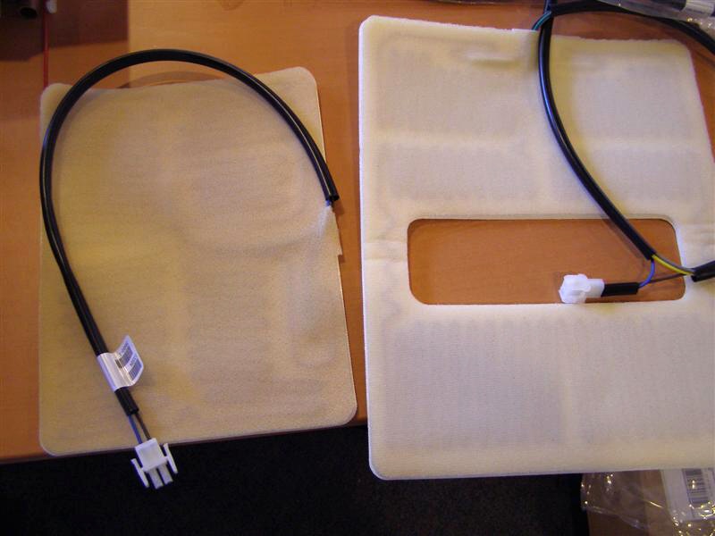
Controller and wiring for one
seat,
These two connect the seat
back and seat cushion together and into the main harness.
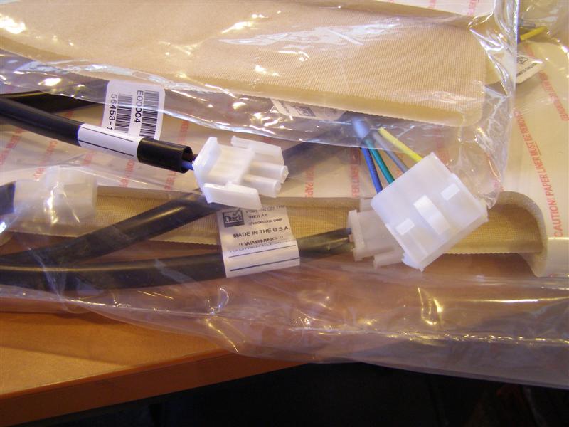
This will be the general idea
but with the harness lower and out the bottom.
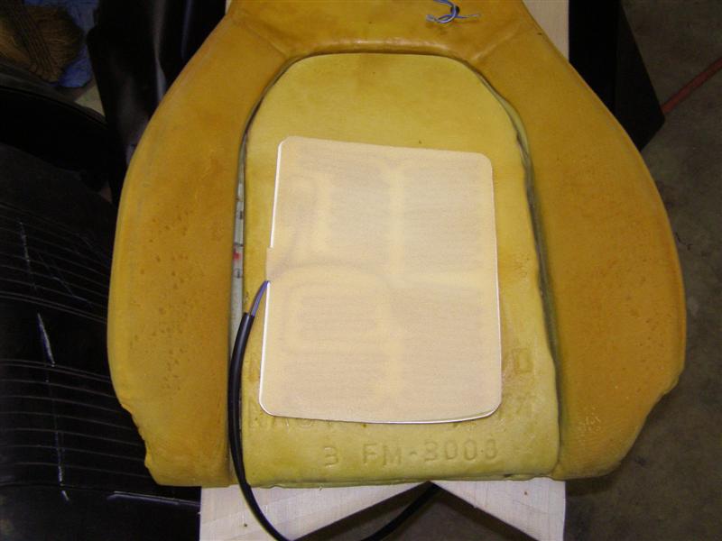
This one goes on the seat
cushion.
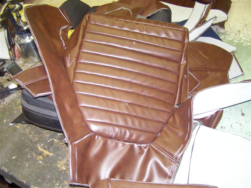
Now back to the upholstery
shop.
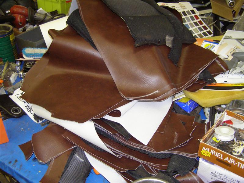
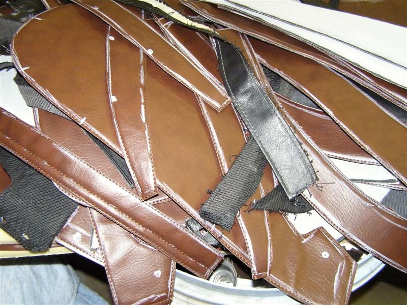
And from this pile of
patterns a set if new covers will emerge. Now all I need
is the seat heaters.
It may not look so great on
this table, but it will when Eddie gets them completed.
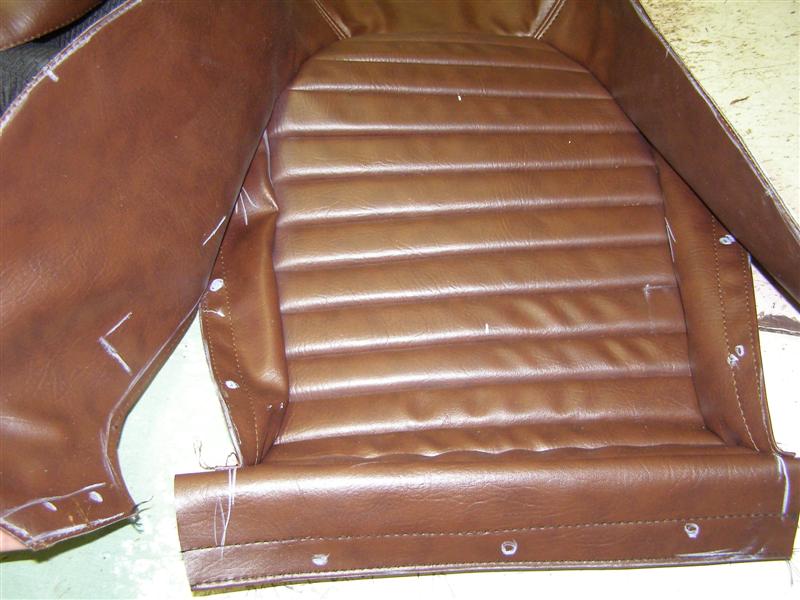
The other seat patterns
taking shape. These will have the backing stitched in
place then trimmed and ready to be fit together.
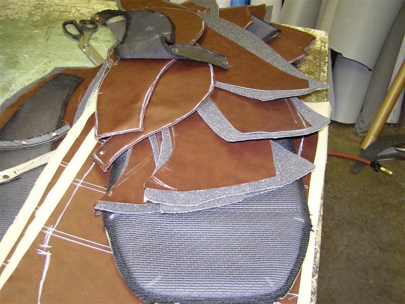
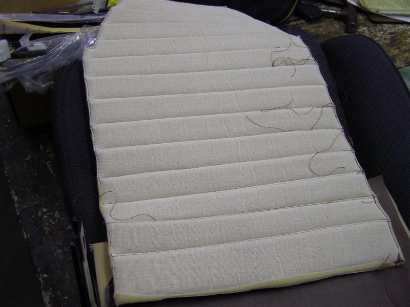
Just the plain backs of the
seats, less backing.
This is one set of seat
patterns cut and trimmed with the backing on.
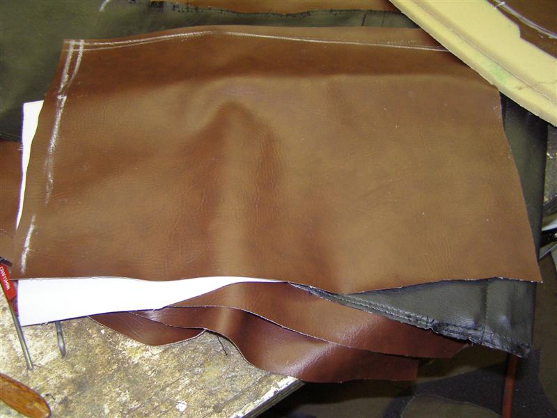
Now I see what Bobby meant
about the "pleating foam."
I delivered the seat speaker
wiring harnesses today with the missing the boxes, screws and
new speakers.
Eddie was busy sewing the
inserts with the rolled and pleated affect.
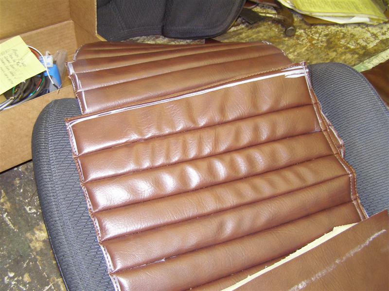
This will be sewn first from
the front and then from the back in what I suppose is called
double stitching for a nice appearance.
Progress as the panels start
to go together.
Now they're starting to look
like seat covers.
And now they're actually on
the cushions.
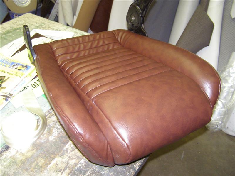
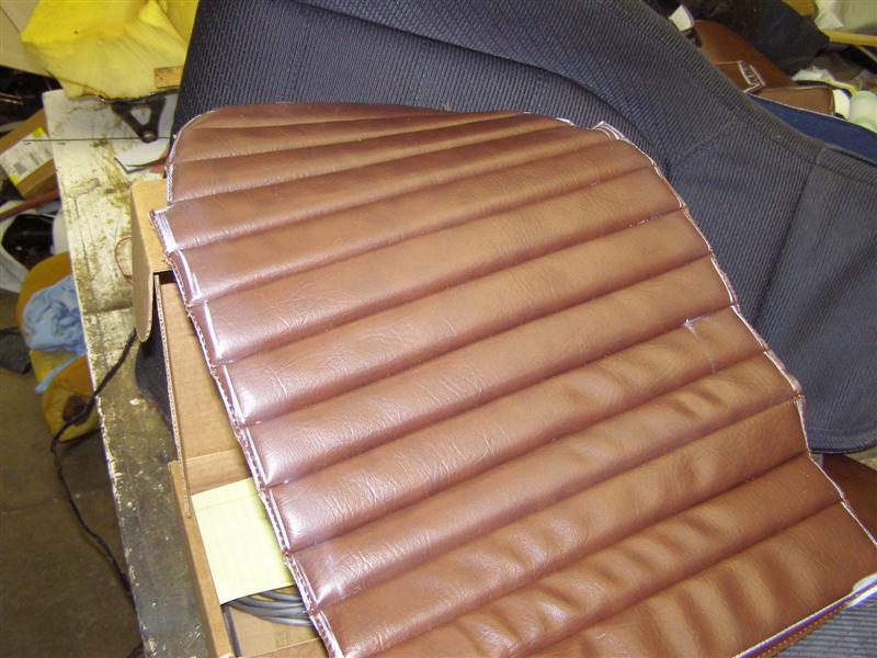
I had to listen to the
"they're not done yet" as I was taking pictures, but I was happy
to see the progress.
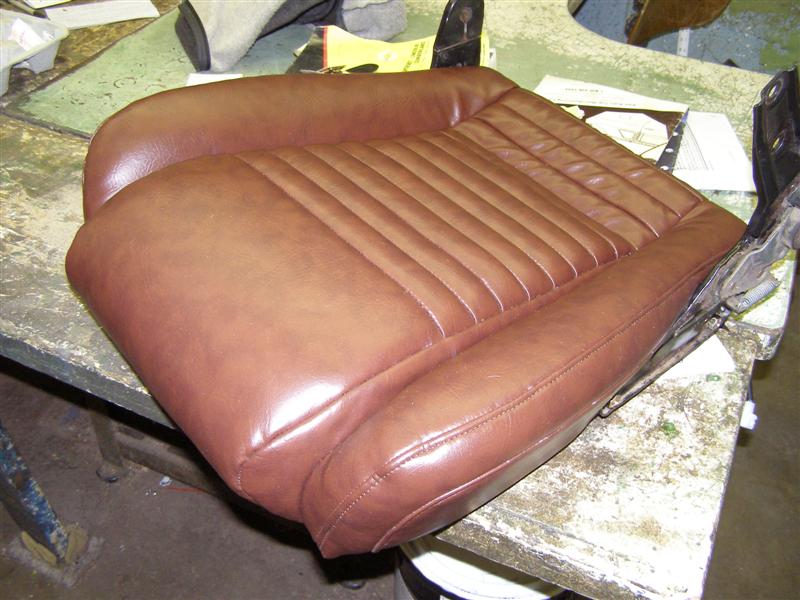
About one half done so far.
A little more fitting with these and tomorrow the seat backs get
covered.
All in all, nice work and I'm
happy.
That's my seat heater wiring
harness coming out of the bottom. I'll make a grommet to
go around that wire so it never
gets pinched and it will be tied down to the frame with enough
travel to allow the seat to move back and forth properly.
The camera flash makes these
look lighter than they really are as seen below without flash.
This will make for a nice
warm back on those cold New England fall days.
The speaker wiring will be
coming out of the channel made at the factory and the heater
harness will come out of the bottom to plug into the cushion
harness.
We I did the fuse panel conversion, I installed a new under the
dash to run the two seats to. Each seat module has it's
own internal relay, so they are protected.
Both harnesses looking for
their mates.
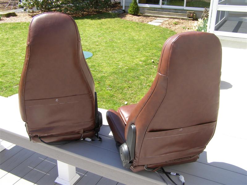
Friday was seat pickup day
and I'm very happy with the results.
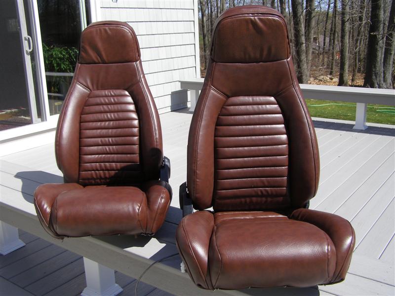
Eddie did a great job and the
seats look terrific. My wife even likes them and she
wasn't sure how this would all work out.
I have a little chalk to
clean up, but the tracks have to go on and I have to get the
wiring all secure and ready to install.
After these are used for a
while, we'll iron out any wrinkles.
Even map pockets on
both like the Miata had.
First install the outer track
on each seat as you do these one at a time. The bolts that
hold them on have 12mm heads.
After the outer is bolted on,
install this wire with the left seat track loose and on your
hand. A little twisting will do it,
then you can bolt the seat track on the inner side.
Remember that the inners have the release levers and the outers
do not.
Don't forget to slide the hog ring back over the cable to keep
it locked down.
Now you can see the finished
track setup on the drivers seat.
This would be the passenger
seat with the tracks all set to go.
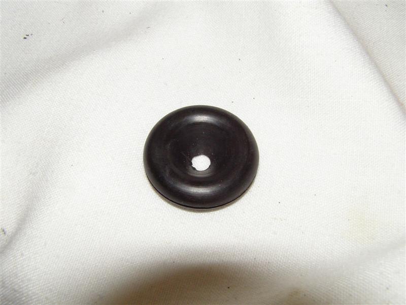
A little talcum spray so that
I don't mix up driver and passenger wires.
This will protect the seat
heater harness from moving around and getting cut in the sharp
seat pan.
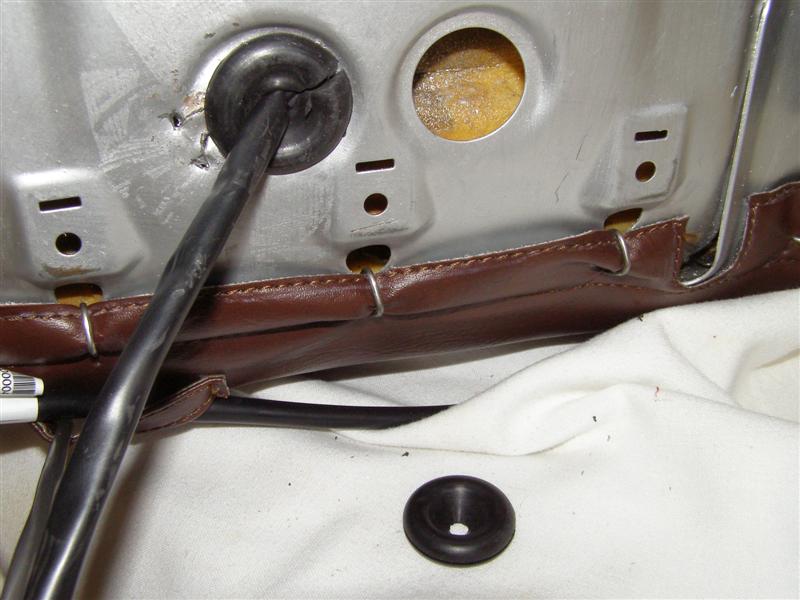
Leftover from a TRF grommet
kit for a TR6. This one will go in the other seat.
Next stop back out to the
garage for installation and harness hook up for the radio and
seat heaters.
First step remove old seats.
Tilting the seats forward shows the forward two bolts that hold
the seats onto the frame.
Take the two rear latch
plates off to get easier access to the rear seat track bolts.
Slide the seat track back to
gain access to the front bolts. What is that sticky junk
on the left track?
Over to the drives seat.
The bolts are staggered with
the outer being a bit more forward than the inner.
These are the four (4) round
spacers from the factory to elevate the tracks above the floor.
Don't loose them, you will be
reusing them.
That one is out, not to get
the right side off the carpet that it's stuck on.
See what one can of Coke will
do if left alone for a year? This track was locked up
solid and I had to chisel it off of the carpet.
One high pressure soap
washing and three trips through the mat cleaner at the car wash
and it is softer, but will not come off.
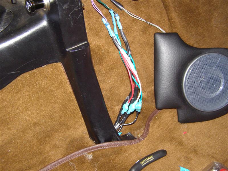
Time to tie in my speaker
wiring harnesses that I made on the passenger side and I'll run
the heater harnesses down the drivers side.
Tedious, but it will be worth
it.
The top connectors split the
rear speakers into three circuits, one for each seat and the
original rear speakers in the rear panel.
The lower connectors are for
the rear panel speakers only, in case I want a quick disconnect
for them.
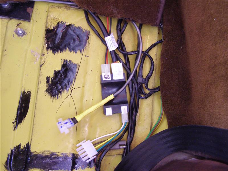
This is the speaker harness
for the driver seat and the module for the seat heater. I
put these all to the rear, so I could bring the wiring in the
seat right out the back.
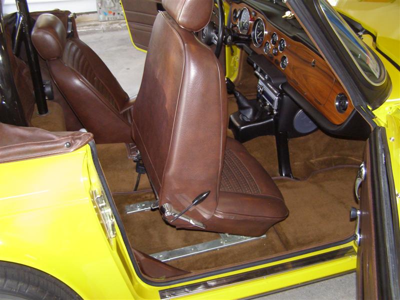
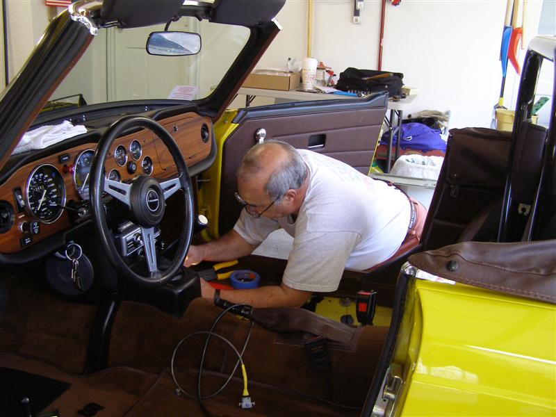
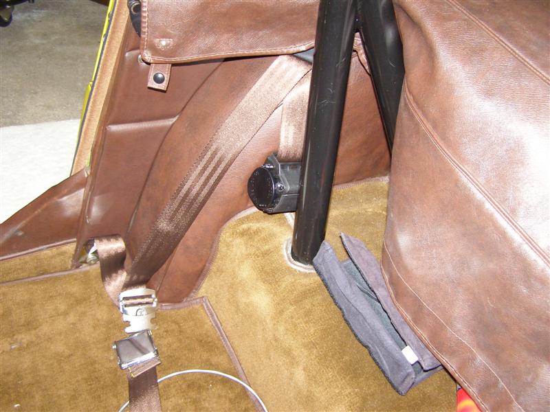
Test fitting of one seat
before I change the seat belts. Which, I think, will help
gain more room for the seats.
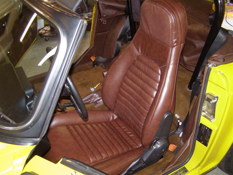
Those hard seat belt latches
are a pain and are in the way. They will be gone soon.
k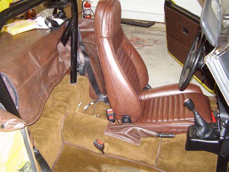
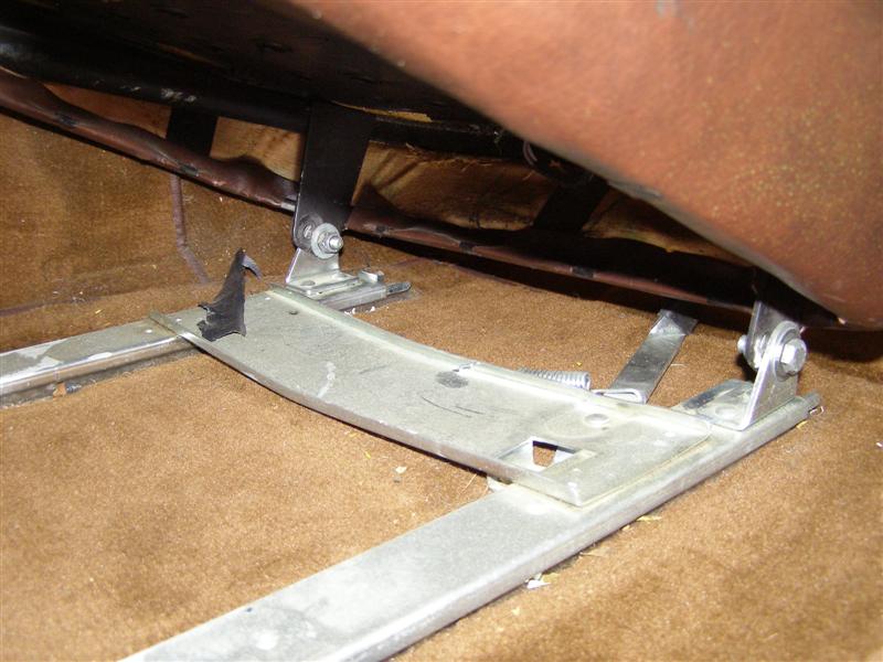
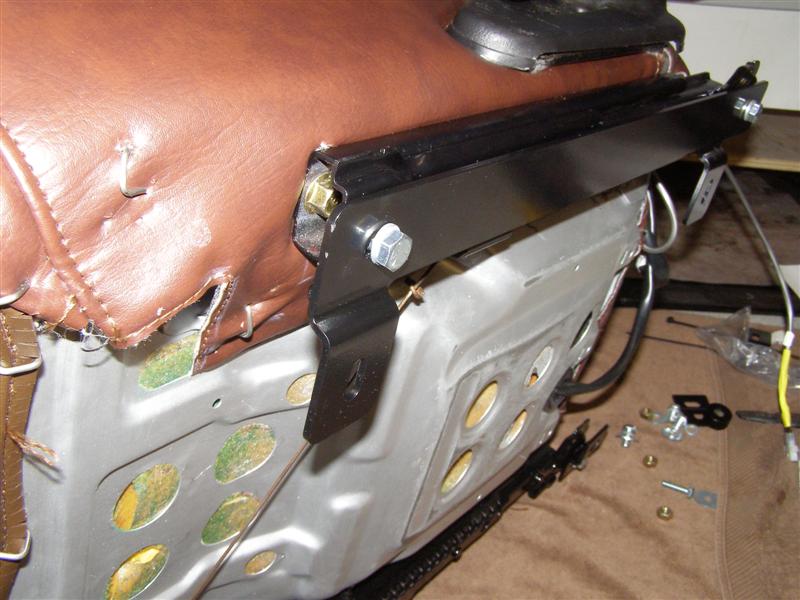
The ARE bracket kit finally
installed, but only finger tight so it can all be moved slightly
as the seats are lined up to the holes in the floor.
This is about the angle that
the inner rear ends up facing when installed.
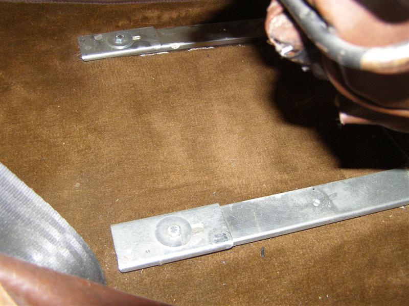
A nice flat, flush fit
against the track.
This is why you have to grind
off the raised edges and make sure the tracks are perfectly
flat.
And a new set of Chestnut
seat belts that have been sitting in the basement for a year
waiting to go in.
Almost done! Three
bolts in each one, but my backs to sore to fight with the last
one tonight.
But the speakers work GREAT.
I'll try the heaters later in the week.
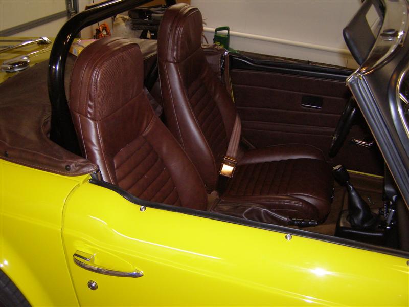
These look better in the day
light than in my fluorescent garage lighting.

Not a bad match, considering
no one would promise a definite match for a 36 year old car.
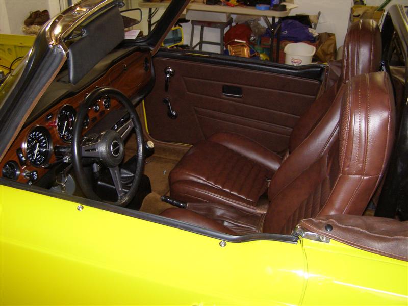
I'll be happy when the last
bolt is in each side of the front seats, but it won't be
tonight.
That's
about it for this project until I get the seat heaters hooked
up. Hung up for now on where to put the switches, but
that's a minor problem.
|